Property
|
Description
|
|
Class
|
|
|
Superclass
|
|
|
Subclass
|
|
|
Definition
|
An instance of this DRM class specifies a unit vector, the
meaning of which is specified by its
vector_type field.
The unit_vector field specifies the
unit vector. For a <DRM Reference Vector> instance
with a <DRM Reference Vector Control Link> component
X, the value of the
unit_vector field is obtained from
X.
The vector_type field specifies the semantic
meaning of the vector data being represented by the
<DRM Reference Vector> instance.
|
|
Class diagram
|
Figure 6.269 —
DRM_Reference_Vector
|
|
Inherited field elements
|
|
Field name
|
Range
|
Field data type
|
None |
|
|
|
|
Field elements
|
|
|
Default field values
|
Default field values for DRM_Reference_Vector
|
Associated to (one-way) (inherited) |
|
Associated to (one-way) |
|
Associated by (one-way) (inherited) |
|
Associated by (one-way) |
|
Associated with (two-way) (inherited) |
|
Associated with (two-way) |
|
Composed of (two-way) (inherited) |
|
Composed of (two-way) |
|
Composed of (two-way metadata) (inherited) |
|
Composed of (two-way metadata) |
|
Component of (two-way) (inherited) |
|
Component of (two-way) |
|
|
Constraints
|
|
|
Clarifications
|
None.
|
|
Example(s)
|
Consider a <DRM Polygon> instance specified in a 3D LSR SRF
for which a data provider wishes to explicitly provide the
surface normal vector so that consumers do not need to calculate
the surface normal when consuming that particular
<DRM Polygon> instance.
The data provider specifies this vector information as a
<DRM Reference Vector> component
of the <DRM Polygon> instance as depicted in
Figure 6.270:
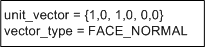
Figure 6.270 — <DRM Reference Vector> surface normal example
Since the <DRM Reference Vector> instance
is a component of a <DRM Polygon> instance, it
specifies a <DRM LSR 3D Location>
component in order to comply with
7.2.61 Required reference vector location.
Consider a <DRM Reference Vector> instance, contained by a
<DRM Polygon> instance, representing a normal vector that is used
for rendering purposes (that is, to calculate colour and shading when
rendering the <DRM Polygon> instance). This
<DRM Reference Vector> instance has a
vector_type of
RENDERING_NORMAL.
Consider a <DRM Polygon> instance F
classified as ECC_FENCE, where F is a
quadrilateral. F is instanced on some
terrain representation, such that the plane of F
is perpendicular to the surrounding terrain.
F has radar cross sections that are dependent
on aspect angles (azimuth and elevation). These aspect angles are
defined with respect to F’s normal vector and
F’s azimuth vector. Consequently,
F has two <DRM Reference Vector>
components as depicted in
Figure 6.271:
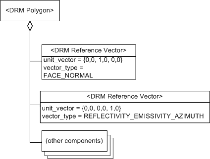
Figure 6.271 — <DRM Reference Vector> radar cross section example
The FACE_NORMAL
<DRM Reference Vector> component is the unit vector that is
perpendicular to the plane of F and points away
from F on its outside face. The azimuth
<DRM Reference Vector> component is the unit vector that lies
in the plane of F and points straight up.
A segment of the road has a retroreflector (a device that reflects emissions
back along the incident path irrespective of its angle of incidence)
on it and is modelled as a <DRM Line> instance. The
<DRM Line> instance has a normal vector that is
perpendicular to it and an azimuth reference parallel to it. This is
sufficient to describe radar cross sections of the road as a function of
aspect angles. However, the normal vector for the infrared bands depends
on the orientation of the retroreflector, not the road. This is because
radars see the road but infrared see the retroreflector. In this example,
the <DRM Line> instance has
four <DRM Reference Vector> components
(radar-normal, radar-azimuth, infrared-normal, and infrared-azimuth).
A normal vector used for reflectivity/emissivity calculations is
represented by a <DRM Reference Vector>
instance with vector_type =
REFLECTIVITY_EMISSIVITY_NORMAL.
A vector specifying the direction of illumination of
a <DRM Infinite Light> instance
is represented by a <DRM Reference Vector>
component with vector_type =
LIGHT_DIRECTION.
|