Table 6.21 — DRM_Blend_Directional_Light

Property

Description

Class

  • <DRM Blend Directional Light>

Superclass

Subclass

  • None.

Definition

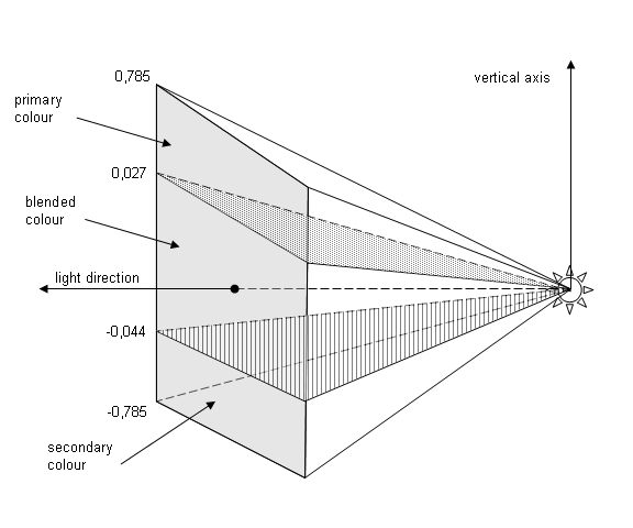
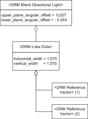
An instance of this DRM class specifies a <DRM Directional Light Behaviour> instance, the intensity of which varies depending on the position of the observer relative to the light’s location, direction, and shape. This light takes the shape of a pyramid, subdivided by two planes. These planes are based at the apex of the pyramid and extend towards the base. They subdivide the pyramid into upper, blend, and lower sections. If the observer is in the upper section, the primary colour is displayed. If the observer is in the lower section, the secondary colour is displayed. If the observer is in the blend section, the colour displayed is a proportional blend of the primary and secondary colours as defined below.

NOTE  The positive and negative ends of the VERTICAL_AXIS vector correspond to upper and lower, respectively.

The upper_plane_angular_offset field specifies, in radians, the angular offset of the plane separating the upper and blend sections of the pyramid. The offset is measured from the given LIGHT_DIRECTION vector of the <DRM Lobe Data> instance along the VERTICAL_AXIS vector of the <DRM Lobe Data> instance.

The lower_plane_angular_offset field specifies, in radians, the angular offset of the plane separating the blend and lower sections of the pyramid. The offset is measured from the given LIGHT_DIRECTION vector of the <DRM Lobe Data> instance along the VERTICAL_AXIS vector of the <DRM Lobe Data> instance.

The upper_plane_angular_offset shall be greater than or equal to the lower_plane_angular_offset. Both planes shall be within the pyramid defined by the given <DRM Lobe Data> instance.

The colour used to display the light is computed as follows.

Let:

U = upper_plane_angular_offset
L = lower_plane_angular_offset
O = observer angular offset
D = colour to display
P = primary colour
S = secondary colour

Then:

Case 1:  O ≥ U

D = P

Case 2:  L < O < U

D = ((O - L) × P + (U - O) × S) / (U - L)

Case 3:  O ≤ L

D = S

Class diagram

Figure 6.20 — DRM_Blend_Directional_Light

Inherited field elements

Field name

Range

Field data type

None


Field elements

Field name

Range

Field data type

upper_plane_angular_offset

[-π, π]

Long_Float

lower_plane_angular_offset

[-π, π]

Long_Float

Default field values

Default field values for DRM_Blend_Directional_Light

Associated to (one-way) (inherited)

  • None.

Associated to (one-way)

  • None.

Associated by (one-way) (inherited)

  • None.

Associated by (one-way)

  • None.

Associated with (two-way) (inherited)

  • None.

Associated with (two-way)

  • None.

Composed of (two-way) (inherited)

Composed of (two-way)

  • None.

Composed of (two-way metadata) (inherited)

  • None.

Composed of (two-way metadata)

  • None.

Component of (two-way) (inherited)

Component of (two-way)

  • None.

Constraints

Clarifications

1The <DRM Lobe Data> component specifies the lobe shape.

Example(s)

  • For an airplane approaching a runway, the colour of the approach lights can change depending on the relationship of the airplane to the correct approach slope as depicted in Figure 6.21.

    Blend Directional Light, Example 1, blend section example

    Figure 6.21 — <DRM Blend Directional Light> blend section example

    This can be represented by a <DRM Blend Directional Light> instance having both a primary and a secondary colour as depicted in Figure 6.22.

    Blend Directional Light, Example 1

    Figure 6.22 — <DRM Blend Directional Light> example

    If the position of the observer is 0,177 radians (approximately 10 degrees) above the LIGHT_DIRECTION vector of the <DRM Lobe Data> instance, the observer will see the primary colour.

    If the position of the observer is 0,027 radians (approximately 1,5 degrees) above the LIGHT_DIRECTION vector, the observer will see the primary colour, since the observer is at the upper edge of the blend section. As the observer moves lower, the amount of primary colour decreases as it is blended with proportionally increasing amounts of the secondary colour. Once the observer reaches -0,009 radians (approximately -0,5 degrees) from the LIGHT_DIRECTION vector in the vertical direction (i.e., towards the negative end of the VERTICAL_AXIS vector), the observer sees the primary and secondary colours blended in equal amounts as the observer is now in the middle of the blend section. As the observer continues to move in the same direction, the amount of primary colour continues to decrease proportionally as the amount of secondary colour increases. When the observer reaches -0,044 radians (approximately -2,5 degrees) from the LIGHT_DIRECTION vector, the observer sees only the secondary colour, as he has now reached the lower edge of the blend section.

    If the position of the observer from the LIGHT_DIRECTION vector is -0,177 radians (approximately -10 degrees) in the vertical direction (i.e., towards the negative end of the VERTICAL_AXIS vector), the secondary colour is seen as the observer is inside the vertical width, in the lower section of the cone.

    If the position of the observer from the LIGHT_DIRECTION vector is -0,884 radians (approximately -50 degrees) in the vertical direction (i.e., towards the negative end of the VERTICAL_AXIS vector), nothing is seen as the observer is outside the pyramid.