7 Reference datums, embeddings, and object reference models
7.1. Introduction
This International Standard specifies reference datums as geometric primitives in position-space that are used to model aspects of object-space through a process termed reference datum binding. A reference datum binding is an identification of a reference datum in position-space with a corresponding constructed entity in object-space (see 7.2). Reference datums for celestial bodies of interest are specified in Annex D.
A normal embedding is a distance-preserving function from position-space to object-space. A normal embedding establishes a position-space model of object-space. The image of a bound reference datum under a normal embedding may or may not coincide with the constructed entity of the reference datum binding. If they coincide, the reference datum binding and the normal embedding are said to be compatible (see 7.3).
A set of bound reference datums can be selected so as to be compatible with only one normal embedding. In this way, a set of bound reference datums with properly constrained relationships can specify a unique normal embedding. Such a constrained set of bound reference datums is called an object reference model. Object reference models that use the same set of reference datum primitives and similar binding constraints are abstracted in the notion of an object reference model template. Object reference model templates provide a uniform method of object reference model specification (see 7.4).
Object reference models for celestial objects of interest are specified in Annex E. For these celestial objects, one object reference model is designated as the reference model for the object. The transformation from each object reference model to the reference model for the object is termed the reference transformation. Time-independent reference transformations are also specified.
Object-specific rules to bind reference datums in a way that is compatible with the binding constraints of an object reference model template are defined in 7.5. These object-specific binding rules are used to provide a uniform method of specifying object reference models for specific dynamically-related celestial bodies.
7.2. Reference datums
7.2.1 Introduction
A reference datum (RD) is a geometric primitive in position-space that is used to model an aspect of object-space through a process termed RD binding. In this International Standard, the reference datum concept is defined for 1D, 2D, and 3D position-spaces. In the 2D and 3D cases, this International Standard specifies a small set of reference datums for use in its own specifications. This set is not intended to be exhaustive. Users of this International Standard may specify additional reference datums by registration in accordance with Clause 13.
7.2.2 Reference datums
In this International Standard, an RD geometric primitive is expressed in terms of analytic geometry in position-space. RDs are designed to correspond to constructed entities of similar geometric type in an object-space through a process called RD binding (see 7.2.5). These geometric types are limited to a point, a directed curve, or an oriented surface. The analytic form of the position-space representation and its corresponding object-space geometric representation are described by category and position-space dimension in Table 7.1. An RD of a given category is specified by the parameters and/or the analytic expression of its position-space representation.
Table 7.1 — RD categories
|
RD category |
Position-space representation |
Object-space |
||
|
1D |
2D |
3D |
||
|
Point |
(a) real a |
(a, b) real a, b |
(a, b, c) real a, b, c |
a point in the object-space |
|
Directed curve |
|
|
|
a curve in the object-space with a designation of direction along the curve |
|
Oriented surface |
|
|
|
a surface in the object-space with a designation of one side as positive |


This International Standard specifies 2D and 3D RDs by RD category in Table 7.4 through Table 7.8. The specification elements of those tables are defined in Table 7.2. 3D RDs based on ellipsoids are described in 7.2.3 and 7.2.4 and specified in Annex D with specification elements defined in Table 7.9. Table 7.3 is a directory of RD specification tables or, in the case of 3D RDs based on ellipsoids, RD specification directories.
Table 7.2 — RD specification elements
|
Element |
Definition |
|
RD label |
The label for the RD (see 13.2.2). |
|
RD code |
The code for the RD (see 13.2.3). |
|
Description |
A description of the RD including any common name for the concept. |
|
Position-space representation |
The analytic formulation of the RD in position-space |
Table 7.3 — RD specification directory
|
Position-space |
RD category |
Table number |
|
2D |
point |
|
|
3D |
point |
|
|
2D |
directed curve |
|
|
3D |
directed curve |
|
|
3D |
oriented surface |
Table 7.8 and Table 7.10 |
Table 7.4 — 2D RDs of category point
|
RD label |
RD code |
Description |
Position-space representation |
|
ORIGIN_2D |
1 |
Origin in 2D |
(0,0) |
|
X_UNIT_POINT_2D |
2 |
x-axis unit point in 2D |
(1,0) |
|
Y_UNIT_POINT_2D |
3 |
y-axis unit point in 2D |
(0,1) |
Table 7.5 — 3D RDs of category point
|
RD label |
RD code |
Description |
Position-space representation |
|
ORIGIN_3D |
4 |
Origin in 3D |
(0,0,0) |
|
X_UNIT_POINT_3D |
5 |
x-axis unit point in 3D |
(1,0,0) |
|
Y_UNIT_POINT_3D |
6 |
y-axis unit point in 3D |
(0,1,0) |
|
Z_UNIT_POINT_3D |
7 |
z-axis unit point in 3D |
(0,0,1) |
Table 7.6 — 2D RDs of category directed curve
|
RD label |
RD code |
Description |
Position-space representation |
|
X_AXIS_2D |
8 |
x-axis in 2D |
|
|
Y_AXIS_2D |
9 |
y-axis in 2D |
|
Table 7.7 — 3D RDs of category directed curve
|
RD label |
RD code |
Description |
Position-space representation |
|
X_AXIS_3D |
10 |
x-axis in 3D |
|
|
Y_AXIS_3D |
11 |
y-axis in 3D |
|
|
Z_AXIS_3D |
12 |
z-axis in 3D |
|
Table 7.8 — 3D RDs of category oriented surface
|
RD label |
RD code |
Description |
Position-space representation |
|
13 |
xy-plane |
|
|
|
14 |
xz-plane |
|
|
|
15 |
yz-plane |
|
7.2.3 Ellipsoidal RDs
The RDs specified in this International Standard include RDs based on oblate ellipsoids, prolate ellipsoids, and tri-axial ellipsoids. These RDs are 3D and of category oriented surface. These RDs are specified based upon certain geometrically-defined parameters. The position-space representations of oblate and prolate ellipsoid RDs are expressed in the form:
When ![]() an RD of this
form is an oblate
ellipsoid RD with major semi-axis a and minor semi-axis b as illustrated in Figure
7.1.
an RD of this
form is an oblate
ellipsoid RD with major semi-axis a and minor semi-axis b as illustrated in Figure
7.1.
Spheres shall be considered as a special case of oblate ellipsoids. If ![]() an oblate ellipsoid RD
may be called a sphere
RD. In this case, the value
an oblate ellipsoid RD
may be called a sphere
RD. In this case, the value ![]() is the radius of the
sphere RD.
is the radius of the
sphere RD.
NOTE In general usage, spheres are a limiting case of oblate, prolate, and tri-axial ellipsoids. To remove ambiguity, in this International Standard spheres are a special case of oblate ellipsoids only.
When ![]() an RD of this
form is a prolate
ellipsoid RD with major semi-axis b and minor semi-axis a, as illustrated in Figure 7.1.
an RD of this
form is a prolate
ellipsoid RD with major semi-axis b and minor semi-axis a, as illustrated in Figure 7.1.
Instead of specifying the parameters of an oblate ellipsoid RD as the major semi-axis a and the minor semi-axis b, it is both equivalent and sometimes convenient to use the major semi-axis a and the flattening f as defined in Equation (2). The minor semi-axis b may be expressed in terms of the major semi-axis a and the flattening f as in Equation (3). The flattening of a sphere RD is zero ( f = 0).
The position-space representation of a tri-axial ellipsoid RD is expressed in the form:
The semi-axes a, b, and c shall be positive non-zero and![]() .
.

Figure 7.1 — Oblate and prolate ellipsoids
7.2.4 RDs associated with physical objects
In the case of ellipsoid RDs intended for modelling physical objects of interest, published parameter values for these RDs are used. The specification of these RDs includes the published ellipsoid parameters and the identification of the associated physical object. The specification elements for physical object RDs are defined in Figure 7.9.
Table 7.9 — Physical object RD specification elements
|
Element |
Specification |
|
|
RD label |
The label for the RD (see 13.2.2). |
|
|
RD code |
The code for the RD (see 13.2.3). |
|
|
Description |
The description including the name as published or as commonly known. |
|
|
Physical object |
The name of the physical object. |
|
|
Parameters |
Oblate ellipsoid case |
Major semi-axis, a Flattening, f |
|
Prolate ellipsoid case |
Minor semi-axis, a Major semi-axis, b |
|
|
Tri-axial ellipsoid case |
x-semi-axis, a y-semi-axis, b z-semi-axis, c |
|
|
RD parameters shall be specified by value or by reference (see 13.2.5). If by value, the value(s) shall be followed by a error estimate expressed in one of the following forms: a) error estimate: unknown b) error estimate: assumed precise c) error estimate (1σ): <parameter name>:<error value> d) error interval: <parameter name> ± <error value> EXAMPLE error
estimate (1σ): If by reference, this specification
element shall express the value(s) and error estimate(s) using the
terminology found in the reference. These terms shall be enclosed in brackets
( {} ). Any parameter value that is not specified in the citation(s) shall be
specified as in the “by value” case. An error estimate for b or for |
||
|
Date |
The date the RD parameters were specified or published. |
|
|
References |
The references (see 13.2.5). |
|
The RDs associated with physical objects are specified in Annex D. Figure 7.10 is a directory of these RDs organized by type of ellipsoid. The semi-axis and radius parameters are unitless in position-space, but are bound to metre lengths when the RD is identified with the corresponding physical object-space constructed entity.
Table 7.10 — Physical RD specification table locations
|
Type of ellipsoid |
RD table |
|
Oblate ellipsoid |
|
|
Sphere |
|
|
Prolate ellipsoid |
|
|
Tri-axial ellipsoid |
Additional RDs associated with physical objects may be specified by registration in accordance with Clause 13.
7.2.5 RD binding
An RD is bound when the RD in position-space is identified with a corresponding constructed entity in object-space. In this context, a "constructed entity" is defined to mean an intrinsic, artificial, measured, or conceptual entity in object-space that is uniquely identifiable within the user's application domain. The term "corresponding" in this context means that each RD is bound to a constructed entity of the same geometric object type. That is, position-space points are bound to identified points in object-space, position-space directed lines to constructed lines or line segments in object-space, position-space directed curves to constructed curves or curve segments in object-space, position-space oriented planes to constructed planes or partial planes in object-space, and position-space oriented surfaces to constructed surfaces or partial surfaces in object-space.
When a curve or surface RD is bound, the radii of curvature on the corresponding constructed entity in object-space shall correspond to the radii of curvature in position-space. In this International Standard, in the case of physical objects, one unit in position-space corresponds to one metre in object-space. In the case of abstract objects, one unit in position-space corresponds to the designated length scale unit in the abstract object-space. In particular, the semi-axes of an ellipsoid RD shall correspond to the semi-axes of the constructed ellipsoid to which it is bound.
If the constructed entity of an RD binding is fixed in position with respect to object-space, then the RD binding shall be called an object-fixed RD binding. This definition assumes that the position of the constructed entity does not change in time by an amount significant for the accuracy and time scale of an application.
EXAMPLE 1 For points on the surface of the Earth, tectonic plate movements are insignificant for many applications.
EXAMPLE 2 An RD X_AXIS_3D is bound to the line segment from the centre of the Earth to the centre of the Sun. This RD binding is not an object-fixed RD binding with respect to the spatial object Earth.
Figure 7.2 illustrates two distinct bindings of a point RD. On the left, it is bound to a specific point in the abstract object-space of a CAD/CAM model. On the right, it is bound to a point in physical object-space that is on an object that has been manufactured from that CAD model.

Figure 7.2 — An RD bound to an abstract object and to a real object
7.3. Normal embeddings of position-space into object-space
7.3.1 Normal embeddings
An embedding is a position-space model of object-space formed by a one-to-one function of positions in position-space to points in object-space. A normal embedding is an embedding that satisfies the following distance-preserving property:
A function E from position-space to object-space is distance-preserving if for any two positions p and q in position-space, the measured distance in object-space from E(p) to E(q) in metres is equal to the Euclidean distance d(p, q).
NOTE 1 As a consequence of the normal distance-preserving property, a normal embedding is also a continuous function, that preserves angles, area, and other geometric properties.

Figure 7.3 — A right-handed normal embedding19
In position-space, the point E(0) is called the origin of the normal embedding E, and the point E(e1) is the x-axis unit point of the normal embedding E. If the dimension of position-space is 2D or 3D, the point E(e2) is the y-axis unit point of the normal embedding E. If the dimension of position-space is 3D, the point E(e3) is the z-axis unit point of the normal embedding E.
A normal embedding of a 3D position-space is right-handed if the directed triangle formed by the three points, x-axis unit point, y-axis unit point, and z-axis unit point, in that sequence, has a clockwise orientation when viewed from the origin of the embedding. Otherwise, the embedding is left-handed. A right-handed normal embedding is illustrated in Figure 7.3. All 3D normal embeddings in this International Standard shall be right-handed.
7.3.2 Specification of 3D similarity transformations
A 3D object-space may have many normal embeddings of 3D position-space.
Given two 3D normal embeddings E1 and E2 into the same object-space, one
embedding can be expressed in terms of the other normal embedding. Given a
position ![]() in
position-space, the normal embedding E2 associates to it a unique point p in object-space. The normal embedding E1 uniquely associates some position
in
position-space, the normal embedding E2 associates to it a unique point p in object-space. The normal embedding E1 uniquely associates some position ![]() to the same point p. This association
of
to the same point p. This association
of ![]() to
to ![]() may be expressed as a
similarity transformation from E2 to E1 (see Figure 4.2). A similarity
transformation is defined as
a transformation on position-space that performs a translation, rotation,
and/or scaling operation.
may be expressed as a
similarity transformation from E2 to E1 (see Figure 4.2). A similarity
transformation is defined as
a transformation on position-space that performs a translation, rotation,
and/or scaling operation.
In general, E2(0) may be displaced
with respect to E1(0)
and the axes of the E2 normal embedding may also be rotated
and/or differently scaled with respect to the axes of the E1 normal embedding (see Figure 7.4). If E1 associates the position ![]() to E2(0),
the similarity transformation from E2 to E1 may be specified in the form of the seven-parameter
transformation:
to E2(0),
the similarity transformation from E2 to E1 may be specified in the form of the seven-parameter
transformation:

where:
|
|
|
|
|
|
|
|
|
|
|
|


and where:
|
|
|
|
|
|
|
|
|
|
|
|
|
|
|
|
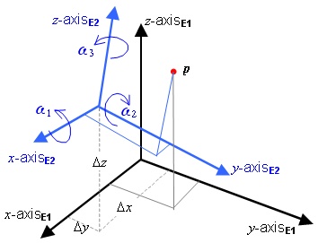
Figure 7.4 — 3D normal embedding relationships
The scale adjustment is needed to account for differing length scales
in abstract object-space. In the case of physical object-space, small non-zero
values of ![]() may be required
to adjust for spatial distortions in empirically estimated data. This is addressed
in 7.4.5.
may be required
to adjust for spatial distortions in empirically estimated data. This is addressed
in 7.4.5.
The convention of viewing the rotations with respect to E1 is the position
vector rotation convention. The coordinate frame rotation convention views rotations with respect to E2 instead of E1. The rotations ![]() in Equation (5)
are position vector rotations. If coordinate frame rotations are used, the
rotations reverse sign (see Figure 7.5).
in Equation (5)
are position vector rotations. If coordinate frame rotations are used, the
rotations reverse sign (see Figure 7.5).
Note 1 Sign reversal does not affect cosine terms in the equation. Only the sine terms reverse sign.

Figure 7.5 — Rotation between E1 and E2 in two conventions
NOTE 2 A small rotation approximation of the seven-parameter transformation is described in Annex B.
The seven-parameter embedding specification of E2 with respect to E1 is defined by the seven-parameter values ![]() in the position vector
rotation convention (as in Equation (5)).
in the position vector
rotation convention (as in Equation (5)).
NOTE
3 In the cases that ![]() the
formula for the transformation from
the
formula for the transformation from ![]() to
to
![]() reduces to a translation
operation
reduces to a translation
operation![]() .
.
7.3.3 Specification of 2D similarity transformations
Given two 2D normal embeddings E1 and E2 into the same 2D object-space, one
embedding can be expressed in terms of the other normal embedding. Given a
position ![]() in
position-space, the normal embedding E2 associates to it a unique point p in object-space. As in the 3D case, this
association may be expressed as a similarity transformation.
in
position-space, the normal embedding E2 associates to it a unique point p in object-space. As in the 3D case, this
association may be expressed as a similarity transformation.
If E1 associates ![]() to
E2(0),
to
E2(0),
![]() is the scale factor, and w is the relative rotation, then the 2D similarity transformation
from E2 to E1 may be specified in the form of the four
parameter transformation:
is the scale factor, and w is the relative rotation, then the 2D similarity transformation
from E2 to E1 may be specified in the form of the four
parameter transformation:

with parameters: ![]()
7.4. Object reference model
7.4.1 Introduction
A set of bound RDs can be selected so as to be compatible with only one normal embedding. In this way, a set of bound RDs with properly constrained relationships can specify a unique normal embedding. Such a constrained set of bound RDs is called an object reference model. Some object reference models use a set of RDs that model application-specific geometric aspects of the object-space. Of particular interest are object reference models that include an oriented surface RD that models a surface significant to the object (see 7.4.2).
A relationship between two or more bound RDs needed to ensure compatibility with a normal embedding is termed a binding constraint (see 7.4.3). Object reference models that use the same set of RD primitives and the same binding constraints are abstracted in the notion of an object reference model template. Object reference model templates provide a uniform method of object reference model specification. If the bound RDs of an object reference model are compliant with the RD set and binding constraints of a particular object reference model template, then the object reference model is said to realize that template (see 7.4.4).
A set of standardized object reference model templates are defined in this International Standard (see 7.4.5). Realizations of these templates are specified in Annex E.
7.4.2 ORM
A normal embedding and an RD binding are compatible if the normal embedding image of the RD primitive is coincident with the points (and direction or orientation, as applicable) of the constructed entity of the RD binding.
EXAMPLE 1 The constructed point in object-space to which RD ORIGIN_3D is bound is the origin of a normal embedding if, and only if, that normal embedding is compatible with the RD binding.
EXAMPLE 2 The directed line constructed in object-space to which RD X_AXIS_3D is bound is the locus of the x-axis image under a compatible normal embedding, and similarly for other axis RDs.
An object reference model (ORM) for a spatial object is a set of bound RDs for which there exists exactly one normal embedding that is compatible with each bound RD in the set. In the 3D case, this unique embedding shall also be right-handed.
An ORM is object-fixed if each of its RD bindings are object-fixed, otherwise it is called object-dynamic. The object-fixed definition assumes that the object itself is not changing in time by an amount significant for the accuracy and time scale of an application. The normal embedding determined by an ORM is, correspondingly, either an object-fixed embedding or an object-dynamic embedding.
EXAMPLE 3 The Sun and the gas giants Jupiter, Saturn, Uranus, and Neptune are not rigid. The ORM specified for the Sun uses RD bindings defined in part by ephemeris and is thus object-dynamic. In the case of the ORMs specified for the gas giants, the object for binding is the magnetic field of the planet, thus these ORMs are object-fixed.
An ORM is often selected to contain an RD of category oriented surface that corresponds to a physical or conceptual surface significant to the modelled spatial object. An RD is chosen and its position with respect to the object is bound so that that the RD instance is a “best fit” to the object in some application-specific sense. In particular, if the RD surface is “fitted” to a specific part of the object surface, the ORM is called a local model. If the RD is selected to best fit the entire surface, the ORM is called a global model.
An ORM may also contain an RD for the purpose of providing a CS binding parameter (see 8.3.2.2). In particular the radius of a sphere RD or the semi-axis values of an oblate ellipsoid RD may be used for this purpose.
An Earth reference model (ERM) is an ORM for which the spatial object is the Earth.
EXAMPLE 4 If the object is a planet, an ORM containing an oblate ellipsoid RD is usually selected to model all or part of the general shape of the planet.
7.4.3 Binding constraint
In an ORM, the existence of a unique and compatible normal embedding depends on establishing certain geometric relationships, called binding constraints, when the RDs are bound.
A binding constraint is a relationship in object-space between the constructed entities of two or more bound RDs, or a size relationship between a reference datum primitive and its corresponding constructed entity. Binding constraint relationships used in this International Standard include:
a) containment of a point in a curve or a surface;
b) containment of a curve in a surface;
c) coincidence of a line with an axis of symmetry of a surface;
d) in the 3D case, the right-handedness of sets of directed lines or oriented planes; or
e) distance measurement in object-space between points.
In this International Standard every abstract object-space has an associated length scale. The term “(scaled) metres” in a binding constraint definition shall mean “metres” in the case of physical objects and shall mean “length scaled to metres with respect to the length scale of object-space” in the case of abstract objects.
7.4.4 ORM template
ORMs that have the same set of RD primitives and that have the same binding constraints are abstracted in the notion of an ORM template. An ORM template specifies how certain sets of RD primitives may be bound to ensure that the resulting set of bound RDs forms an ORM. An ORM template can be used to conveniently specify multiple ORMs.
An ORM template (ORMT) is a set of RDs and binding constraints such that, for a given object-space, whenever the RDs in the set are bound in compliance with the set of binding constraints, then that bound set of RDs forms an ORM.
An ORM is a realization of an ORMT if
1) the RDs of the ORM match the RD set of the ORMT, and
2) the RD bindings of the ORM are compliant with the binding constraints of the ORMT.
This International Standard specifies a set of ORMTs for 2D and 3D position-space in Table 7.14. The specification elements are defined in Table 7.11. Additional ORMTs may be registered in accordance with Clause 13. Table 7.12 is a directory of ORMT specification tables.
Table 7.11 — ORMT specification elements
|
Element |
Definition |
|
|
ORMT label |
The label for the ORMT (see 13.2.2). |
|
|
ORMT code |
The code for the ORMT (see 13.2.3). |
|
|
ORMT specification |
Description |
A description of an ORM realization of the template. |
|
RD set |
A list of RDs in the set. |
|
|
Binding constraints |
Binding constraints. |
|
|
Notes |
Optional notes. |
|
Table 7.12 — ORMT specification directory
|
Position-space |
Table number |
|
2D |
|
|
3D |
Table 7.13 — 2D ORMT specifications
|
ORMT label |
ORMT code |
ORMT specification |
|
1 |
Description: x- and y-axes determined by directed perpendicular lines passing through the origin RD set: RD 1) RD ORIGIN_2D RD 2) RD X_AXIS_2D RD 3) RD Y_AXIS_2D Binding constraints: BC 1) The constructed point bound to RD 1 shall be contained in the constructed directed line bound to RD 2 and the constructed directed line bound to RD 3. BC 2) The constructed directed lines bound to RD 2 and RD 3 shall be perpendicular. Notes: 1) The constructed point bound to RD 1 determines the origin of the normal embedding. 2) The perpendicular directed lines passing through the origin uniquely determine the x-axis and y-axis of the normal embedding. |
Table 7.14 — 3D ORMT specifications
|
ORMT label |
ORMT code |
ORMT specification |
|
2 |
Description: 3D sphere with designated directional axis and xz-plane RD set: RD 1) The sphere RD with radius r. RD 2) RD Z_AXIS_3D RD 3) RD XZ_PLANE_3D Binding constraints: BC 1) The constructed directed line bound to RD 2 shall contain the centre of the constructed sphere bound to RD 1. BC 2) The constructed plane bound to RD 3 shall contain the constructed directed line bound to RD 2. BC 3) The radius of the constructed sphere bound to RD 1 shall be r (scaled) metres. Notes: 1) The centre of the constructed sphere bound to RD 1 determines the origin of the normal embedding. 2) The constructed directed line bound to RD 2 passing through the origin of the normal embedding uniquely determines the z-axis of the normal embedding. 3) The plane through the origin of the normal embedding perpendicular to the z-axis of the normal embedding determines the xy-plane of the normal embedding. The constructed plane bound to RD 3 determines the xz-plane of the normal embedding. The intersection of the constructed xz-plane with the xy-plane is the locus of the x-axis of the normal embedding. The positive side of the xz-plane is designated in the binding and together with the direction of the z-axis of the normal embedding determines the direction of the x-axis of the normal embedding. 4) The line perpendicular to the xz-plane of the normal embedding through the origin of the embedding determines the locus of the y-axis of the normal embedding. Its direction is determined by the right-handedness of the normal embedding. 5) The distance binding constraint BC 3 is required for compatibility with a normal embedding. |
|
|
3 |
Description: Oblate ellipsoid with designated minor axis direction and xz-plane RD set: RD 1. The oblate ellipsoid RD with major semi-axis a and minor semi-axis b RD 2. RD Z_AXIS_3D RD 3. RD XZ_PLANE_3D Binding constraints: BC 1. The spatial plane RD 3 shall contain the minor axis of the spatial oblate ellipsoid RD 1. BC 2. The spatial z-axis RD 2 shall coincide with the minor axis of the spatial oblate ellipsoid RD 1. BC 3. The RD 1 length of the spatial major semi-axis shall be a (scaled) metres and the length of the spatial minor semi-axis shall be b (scaled) metres. Notes: 1) The centre of the constructed oblate ellipsoid bound to RD 1 determines the origin of the normal embedding. 2) The constructed directed line bound to RD 2 passing through the origin (as required by BC 1) uniquely determines the z-axis of the normal embedding. 3) The z-axis of the normal embedding determines the xy-plane as the perpendicular plane through the origin of the normal embedding. BC 2 requires the bound xz-plane to contain the z-axis. The line formed by the intersection of the bound xz-plane with the xy-plane is the x-axis line. The positive side of the constructed plane bound to RD 3 determines the xz-plane and together with the direction of the z-axis determines the direction of the x-axis. 4) The y-axis is determined by the required right-handedness of the normal embedding. 5) The distance binding constraint BC 3 is required for compatibility with a normal embedding. |
|
|
4 |
Description: 3D prolate ellipsoid with designated major axis direction and xz-plane RD set: RD 1. The prolate ellipsoid RD with minor semi-axis a and major semi-axis b. RD 2. RD Z_AXIS_3D RD 3. RD XZ_PLANE_3D Binding constraints: BC 1. The spatial plane shall contain the major axis of the spatial prolate ellipsoid. BC 2. The spatial z-axis shall coincide with the major axis of the spatial prolate ellipsoid. BC 3. The length of the spatial major semi-axis shall be b (scaled) metres and the length of the spatial minor semi-axis shall be a (scaled) metres. |
|
|
5 |
Description: 3D tri-axial ellipsoid with designated z-axis direction and xz-plane RD set: RD 1. The tri-axial ellipsoid RD with x-semi-axis a, y-semi-axis b, and z-semi-axis c. RD 2. RD Z_AXIS_3D RD 3. RD XZ_PLANE_3D Binding constraints: BC 1. The spatial plane shall contain the z-axis of the spatial tri-axial ellipsoid. BC 2. The spatial z-axis shall coincide with the z-axis of the spatial tri-axial ellipsoid. BC 3. The length of the spatial x-semi-axis shall be a (scaled) metres, spatial y-semi-axis shall be b (scaled) metres, and the length of the spatial z-semi-axis shall be c (scaled) metres. |
|
|
6 |
Description: x- and y-axes determined by directed perpendicular lines passing through the origin RD set: RD 1) RD ORIGIN_3D RD 2) RD Z_AXIS_3D RD 3) RD X_AXIS_3D Binding constraints: BC 1) The constructed point bound to RD 1 shall be contained in the constructed directed line bound to RD 2 and the constructed directed line bound to RD 3. BC 2) The constructed directed lines bound to RD 2 and RD 3 shall be perpendicular. Notes: 1) The constructed point bound to RD 1 determines the origin of the normal embedding. 2) The perpendicular directed lines passing through the origin uniquely determine the z-axis and x-axis of the normal embedding. 3) The y-axis is determined by the required right-handedness of the normal embedding. |
|
|
7 |
Description: Sphere with two directed perpendicular lines passing through the centre of the sphere RD set: RD 1) RD ORIGIN_3D RD 2) RD Z_AXIS_3D RD 3) RD X_AXIS_3D RD 4) The sphere RD with radius r Binding constraints: BC 1) The constructed point bound to RD 1 shall be contained in the constructed directed line bound to RD 2 and the constructed directed line bound to RD 3. BC 2) The constructed directed lines bound to RD 2 and RD 3 shall be perpendicular. BC 3) The centre of the constructed sphere bound to RD 4 shall be coincident with the point bound to RD 1. BC 4) The radius of the constructed sphere bound to RD 4 shall be r (scaled) metres. Notes: 1) The point bound to RD 1 determines the origin of the normal embedding. 2) The perpendicular directed lines passing through the sphere centre uniquely determine the z-axis and x-axis of the normal embedding. 3) The y-axis is determined by the required right-handedness of the normal embedding. 4) The distance binding constraint BC 4 is required for compatibility with a normal embedding. 5) The sphere RD is included to provide a CS binding parameter (radius). See 7.4.2 |
|
|
8 |
Description: Oblate ellipsoid with designated centre, minor axis direction and xz-plane RD set: RD 1) RD ORIGIN_3D RD 2) RD Z_AXIS_3D RD 3) RD XZ_PLANE_3D RD 4) The oblate ellipsoid RD with major semi-axis a and minor semi-axis b Binding constraints: BC 1) The constructed point bound to RD 1 shall be contained in the constructed directed line bound to RD 2. BC 2) The spatial plane RD 3 shall contain the constructed directed line bound to RD 2. BC 3) The minor axis of the spatial oblate ellipsoid RD 4 shall be coincident with the directed line bound to RD 2 and the ellipsoid centre shall coincide with the point bound to RD 1. BC 4) The RD 4 length of the spatial major semi-axis shall be a (scaled) metres and the length of the spatial minor semi-axis shall be b (scaled) metres.. Notes: 1) The centre of the constructed sphere bound to RD 1 determines the origin of the normal embedding. 2) The constructed directed line bound to RD 2 passing through the origin uniquely determines the z-axis of the normal embedding. 3) The z-axis of the normal embedding determines the xy-plane as the perpendicular plane through the origin of the normal embedding. BC 2 requires the bound xz-plane to contain the z-axis. The line formed by the intersection of the bound xz-plane with the xy-plane is the x-axis line. The positive side of the constructed plane bound to RD 3 determines the xz-plane and together with the direction of the z-axis determines the direction of the x-axis. 4) The y-axis is determined by the required right-handedness of the normal embedding. 5) The distance binding constraint BC 4 is required for compatibility with a normal embedding. 6) The oblate ellipsoid RD is included to provide a CS binding parameters (major and minor semi-axes). See 7.4.2 |
|
|
9 |
Description: Origin determined by the intersection of three planes RD set: RD 1. RD XZ_PLANE_3D RD 2. RD XY_PLANE_3D RD 3. RD YZ_PLANE_3D Binding constraints: BC 1. The spatial planes shall be pair-wise perpendicular. BC 2. Collective orientations shall be right-handed. Notes: 1) The intersection of all three planes RD 1, RD 2, and RD 3 determine the origin of the normal embedding. 2) The intersection of the xz-plane RD 1 and the xy-plane RD 2 determine the line of the x-axis. 3) The positive side designations of the two planes RD 1 and RD 2 together with the right-handedness requirement determines the positive x-axis direction. The directed line and the origin point determine the x-axis of the normal embedding. 4) The z- and y-axes of the normal embedding are similarly determined. 5) The collective orientation binding constraint BC 2 is required for compatibility with the right-handedness requirement. |
The specification of an ORMT does not determine a normal embedding. A normal embedding is determined when an ORMT is realized as an ORM.
The methods and techniques of binding the RDs of an ORMT realization draw from disciplines ranging from geometry to astronomy, surveying, geophysics, and satellite geodesy. In general, there are many ways to realize an ORMT for a spatial object. Techniques and methodologies for binding RD components are outside of the scope of this International Standard. The ORM concept is designed to be general enough to encompass these many application domains. As an illustration of the generality of this concept, the following Example outlines a method used in geodesy to define the RD bindings of an ORMT OBLATE_ELLIPSOID realization.
EXAMPLE The North American Datum 1927 may be specified as a realization of the ORMT OBLATE_ELLIPSOID (see Table 7.14). The oblate ellipsoid RD component is RD CLARKE 1866 in Table D.2. The binding of this RD and the other two RD components in the Earth object-space may be defined as follows:
a) the direction of the RD Z_AXIS_3D is identified as the north direction of the Earth’s rotational axis,
b) a position (latitude 39º 13’ 26,686” N) on the oblate ellipsoid RD is identified to a position in the Earth object-space (Meades Ranch, Kansas, US),
c) the direction of the surface normal to the ellipsoid at the identified point is specified ( χ = -1,32 ξ = 1,93), and
d) the direction of the positive xz-plane normal is indirectly determined by specifying the longitude of Meades Ranch (98º 32’ 30,506” W).
Items a) through c) determine a unique oblate ellipsoid surface in the object-space of the Earth. The equatorial plane of the oblate ellipsoid is (by compatibility with the oblate ellipsoid surface generating function) the xy-plane, and its intersection with the oblate ellipsoid axis of rotation determines the origin point and the z-axis. Specification (d) together with the origin and the xy-plane determine the x-axis. Since there is one, and only one, oriented yz-plane that is both perpendicular to the xz-plane and right-handed compatible, the right-handed normal embedding is uniquely determined (see Figure 7.6).
This Example is based on a published specification of the North American Datum 1927. However, the methodology used to select the point in b) and determine the surface normal direction c) at that point was a complex process involving a mathematical best fit of the Clarke 1866 ellipsoid to a network of geodetic survey control points spanning the continental United States.
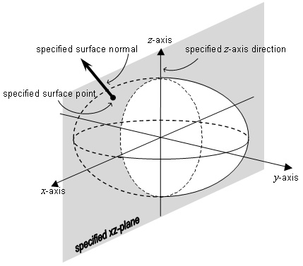
Figure 7.6 — Oblate ellipsoid ORMT binding
7.4.5 Standardized ORMs
The ORMs specified in this International Standard, are ORMT realizations. Standardized ORMs shall include:
a) a specification of the spatial object and optionally a region in object-space,
b) a specification of the ORM template,
c) a specification of the ellipsoid RD (if any), and
d) the binding year if the spatial object is a physical object.
A standardized ORM does not include a specification of the binding of its RD components. The binding specification is not directly needed for the scope of this International Standard. An ORM indirectly designates a unique normal embedding. A specification of an ORM normal embedding is important when two or more ORMs have been specified for the same spatial object. To inter-convert between spatial relationships with respect to two different normal embeddings, one normal embedding shall be expressed in terms of the other normal embedding by means of a similarity transformation, or both shall be expressed in terms of a third (reference) normal embedding by means of a similarity transformation for each ORM with respect to a third (reference) ORM.
If two or more object-fixed ORMs for the same object are specified (or registered), one of the ORMs shall be designated as the reference ORM for that object.
A reference transformation (RT) for an ORM is a similarity transformation from the ORM normal embedding to the normal embedding of the reference ORM for that object, ORMR. The reference transformation for an ORM, ORMS, shall be denoted by HSR (see Table 10.1).
For 3D ORMs, a reference transformation shall be specified by the seven parameters of the corresponding seven-parameter embedding specification. For 2D ORMs, a reference transformation shall be specified by the four parameters of the corresponding four-parameter embedding specification.
Standardized object-fixed ORMs shall specify at least one reference transformation.
Some ERMs that are specified in Table E.5 are based on local geodetic datums. Historic local geodetic datums may exhibit distortions with respect to the reference ERM. In these cases, an RT specified by the seven-parameter transformation of the ERM is an approximation based on empirical measurements. In some of these cases, similarity transformation parameters for approximations based on different sets of measurements and/or sub-regions appear as multiple RT entries in Table E.6. In those cases, the RT labels shall share a common prefix derived from the name of the related local geodetic datum.
NOTE
1 The scale adjustment component of the seven-parameter specification is
needed to account for differing length scales in abstract object-space.
Theoretically, ![]() for two
normal embeddings of a physical object-space. In practice, when the embeddings
are indirectly determined by the RD bindings of an ORM, the determination of
the parameters is an approximation that is the result of a mathematical best
fit and the seventh parameter (
for two
normal embeddings of a physical object-space. In practice, when the embeddings
are indirectly determined by the RD bindings of an ORM, the determination of
the parameters is an approximation that is the result of a mathematical best
fit and the seventh parameter (![]() )
is used to provide an additional degree of freedom to achieve the desired
accuracy in the region of interest. In the case of the object Earth, published
values for
)
is used to provide an additional degree of freedom to achieve the desired
accuracy in the region of interest. In the case of the object Earth, published
values for ![]() are typically
one part per million in magnitude (10-6) or smaller.
are typically
one part per million in magnitude (10-6) or smaller.
A directory of reference ORMs is provided in Table E.1. The reference ORM for the Earth is ORM WGS_1984. This ORM is an Earth-fixed global model. The actual binding definition of ORM WGS_1984 (see [83502S] ) is a realization of ORMT BI_AXIS_ORIGIN_3D. However, for purposes of this International Standard, the RD WGS_1984 is associated with this ORM, so that its ORM specification is a realization of ORMT OBLATE_ELLIPSOID.
The elements of an ORM specification are defined in Table 7.15. Standardized ORMs are specified in Annex E. Additional ORMs may be registered in accordance with Clause 13.
Table 7.15 — ORM specification elements
|
Element |
Definition |
|
ORM label |
The label for the ORM (see 13.2.2). |
|
ORM code |
The code for the ORM (see 13.2.3). |
|
Published name |
The name(s) given to the concept embodied in this ORM in the reference(s). |
|
Reference ORM |
The label of the reference ORM for this object. If this ORM is the reference ORM for this object, then this specification element shall contain the phrase “This is the reference ORM for ” followed by the object name. If no object-fixed ORM specification exits, this specification element shall contain the string “none ”. |
|
Binding information |
Case: Object-fixed ORM for a physical object If the spatial object is a physical object, the date that the ORM RD components were bound in object-space. If the ORM is based on ORMT OBLATE_ELLIPSOID, a significant location contained in the x-positive xz-half-plane of the normal embedding shall be specified. In cases where the spatial object is the Earth, this location shall be understood to be Greenwich, UK, unless otherwise specified. Case: Dynamic ORM for a physical object If the ORM is based on ORMT BI_AXIS_ORIGIN_3D and if the ORM binding complies with a standard object binding rule set, the label of that object binding rule set (see 7.5). If the ORM is a time-fixed (object-fixed) instance of a dynamic ORM, the date that the ORM RD components were bound in object-space. Case: ORM for an abstract object The string “none”. All cases: Optional binding notes. |
|
Region |
The approximate subset of object-space to which the model applies, expressed as either a spatial extent or the description as specified in the reference. |
|
ORMT |
The label of the ORM template for this ORM. |
|
RD parameterization |
The label of the ellipsoidal RD, if any; otherwise “N/A”. |
|
References |
The references (see 13.2.5), or “none” if defined in this International Standard. |
For each object-fixed ORM there shall be specified one or more RTs that transform the ORM to the reference ORM of the ORM spatial object. The elements of an RT specification are defined in Table 7.16. Standardized RTs are specified in Annex E. Additional RTs may be registered in accordance with Clause 13. The standard ORM for an abstract space of a given dimension specifies only an identity RT. Graphical applications use ad hoc transformations to scale, rotate, and translate one abstract space with respect to another as needed in an application. The API (Clause 11) provides support for non-standardized RTs.
Table 7.16 — Reference transformation specification elements
|
Element |
Definition |
|
ORM label |
The label of the standardized ORM that this RT transforms. |
|
RT label |
The label for the RT (see 13.2.2). |
|
RT code |
The code for the RT (see 13.2.3). |
|
RT region |
A description of the extent and/or the spatial bounds of the region for which this reference transformation is applicable. |
|
RT parameters |
The values of the seven parameters shall be specified by value or by reference (see 13.2.5). If by value, the values of the seven parameters a) error estimate: unknown b) error estimate: assumed precise c) error estimate (1σ): <parameter name>:<error value> EXAMPLE error
estimate (1σ): If by reference, this specification element shall contain a
citation(s) for the values of the
seven parameters To avoid loss of
precision, NOTE The rotations |
|
Date published |
The date that the RT was published. |
|
References |
The references (see 13.2.5), or “none” if defined in this International Standard. |
If an ORM is the reference ORM of a spatial object, then it shall have
an RT with the RT label containing the string “IDENTITY”, the RT parameters of
that RT shall be ![]() , and
there shall be no error estimate. These reference ORM identity RTs are labelled
and coded to provide uniform treatment of all object-fixed ORMs in the API (see
Clause 11)
, and
there shall be no error estimate. These reference ORM identity RTs are labelled
and coded to provide uniform treatment of all object-fixed ORMs in the API (see
Clause 11)
If a 3D ORM is not the reference ORM of a spatial object, and the RT
parameters for it are ![]()
![]() within the limits of
precision in measurement and associated errors, then the RT label shall contain
the string “IDENTITY_BY_MEASUREMENT”.
within the limits of
precision in measurement and associated errors, then the RT label shall contain
the string “IDENTITY_BY_MEASUREMENT”.
If a 3D ORM is not the reference ORM of a spatial object, and the RT
parameters for it are ![]()
![]() by intent, then the RT
label shall contain the string “IDENTITY_BY_DEFAULT”.
by intent, then the RT
label shall contain the string “IDENTITY_BY_DEFAULT”.
NOTE 2 In the case of Earth-fixed ERM bindings axis rotations are either zero, or are very small with the following exceptions:
a)
Cases for which the xz-plane does
not contain Greenwich, UK have
relatively large ![]() rotations.
rotations.
b)
The Earth-fixed approximations of
celestiomagnetic ERMs have large ![]() rotations
(see “GEOMAGNETIC” entries in Table 7.32).
rotations
(see “GEOMAGNETIC” entries in Table 7.32).
NOTE 3 A geodetic datum that is global or geocentric is used as a basis for establishing a geocentric SRF (see 8.5.2). If geocentric coordinates are associated to a 3D linear embedding, then such a datum is conceptually equivalent to an ERM. The WGS 84 global datum (see [83502T]) is conceptually equivalent to the ORM WGS_1984 in Table E.5.
7.5. Object binding rules for ORMT BI_AXIS_ORIGIN_3D realizations
7.5.1 Object binding rule set
ORMs for planets, satellites, and other celestial bodies include object-dynamic ORMs based on ORMT BI_AXIS_ORIGIN_3D. Many of these object-dynamic ORMs share common rules for the binding of ORMT BI_AXIS_ORIGIN_3D components based on physical characteristics and spatial arraignments of the applicable celestial bodies. To facilitate uniform specification of these ORMs, the concept of an object binding rule set for an ORMT BI_AXIS_ORIGIN realization is defined.
An object binding rule set (OBRS) for ORMT BI_AXIS_ORIGIN_3D shall be comprised of:
a) an object binding rule set name,
b) a label and code,
c) object restrictions that delineate the object-spaces for which the object binding rules apply, and
d) a set of object binding rules for the RD components of ORMT BI_AXIS_ORIGIN_3D,
where an object binding rule for an ORMT is an object-space specific restriction for the binding of a single RD in the RD set of the ORMT. The set of object binding rules (d) shall comply with the binding constraints of the ORMT.
The specification elements for an OBRS for ORMT BI_AXIS_ORIGIN_3D are defined in Table 7.17.
Table 7.17 — OBRS for ORMT BI_AXIS_ORIGIN_3D specification elements
|
Element |
Definition |
|
OBRS label |
The label for the OBRS (see 13.2.2). |
|
OBRS code |
The code for the OBRS (see 13.2.3). |
|
OBRS name |
A descriptive name. |
|
Object restrictions |
A specification of a set of objects for which the object binding restrictions apply. |
|
Object binding rules |
A specification of the binding rules. |
|
References |
Optional references (see 13.2.5). |
This International Standard provides a collection of OBRS specifications as identified in Table 7.18. Additional OBRS specifications may be registered in accordance with Clause 13.
Table 7.18 — OBRS for ORMT BI_AXIS_ORIGIN_3D specification directory
|
OBRS name |
Table number |
|
equatorial inertial |
|
|
solar ecliptic |
|
|
solar equatorial |
|
|
heliocentric Aries ecliptic |
|
|
heliocentric planet ecliptic |
|
|
heliocentric planet equatorial |
|
|
celestiomagnetic |
|
|
solar magnetic ecliptic |
|
|
solar magnetic dipole |
An OBRS name may be used to describe an ORM that that is compliant with the named OBRS. Thus a "celestiomagnetic ORM" denotes an ORM realization of ORMT BI_AXIS_ORIGIN_3D for an object-space that satisfies the celestiomagnetic OBRS object restrictions and whose RD bindings comply with the celestiomagnetic OBRS object binding rule set.
Several OBRS specifications in Table 7.18 are described using one or more of the following terms: rotational northwards, vernal equinox, inertial direction, quasi-inertial direction, first point of Aries, and Aries true of date. These terms are defined as follows:
The term rotational northwards, as used with respect to a rotating object, shall mean in a direction making an acute angle with respect to the direction from the centre of the object to its rotational north pole.
The ecliptic plane and the plane containing the Sun and parallel to the equatorial plane of a planet intersect in a line. An equinox is one of the two points of intersection between this line and the orbit of the planet. The vernal equinox is the equinox at which the direction from the planet to the Sun begins to ascend to the northern side of the equatorial plane.
An inertial direction is a direction with respect to the universe that is time invariant. A quasi-inertial direction is a direction that changes relatively slowly with respect to the universe.
At any given epoch as defined in 6.2.1, the direction of the Sun at the vernal equinox is fixed with respect to the Milky Way and other (detectible) galaxies. In the case of the Earth, the first point of Aries is the direction from the vernal equinox to the Sun. The current first point of Aries is termed Aries true of date.
NOTE The effects of precession and nutation on the spin axis of a planet cause this direction to change over time. The change in direction of the first point of Aries is very slow (approximately one full rotation in 26 000 years).
EXAMPLE The first point of Aries at a given epoch is an inertial direction, and Aries true of date is a quasi-inertial direction.
7.5.2 Equatorial inertial
The equatorial inertial OBRS is specified in Table 7.19. See also Figure 7.7.
Table 7.19 — Equatorial inertial OBRS
|
Element |
Value |
|
OBRS label |
|
|
OBRS code |
1 |
|
OBRS name |
|
|
Object restrictions |
A planet in the solar system for which the ecliptic plane is distinct from the equatorial plane. |
|
Object binding rules |
1) The RD ORIGIN_3D is the mass-centre of the planet. 2) The RD X_AXIS_3D points in the direction of the Sun when the planet is at its vernal equinox. 3) The RD Z_AXIS_3D is parallel to the rotational axis and points in the direction of rotational northwards. |
|
References |
[SEID] |
The axis directions are quasi-inertial, but vary with respect to any object-fixed ORM for the planet.
In the case of ORM EARTH_INERTIAL_J2000r0, the International Earth Rotation Service (see [IERS]) specifies a very precise transformation to the ORM WGS_1984 reference embedding with a matrix whose coefficients represent the effects of polar motion, the Earth's rotation, nutation and precession20.
Under the assumption that the ORM z-axis and ORM WGS_1984 z-axis are parallel, the transformation simplifies to a single rotation matrix. This simplified form is described in Annex B.
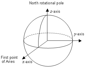
Figure 7.7 — Equatorial inertial OBRS
Three equatorial inertial ERMs labelled ORM EARTH_INERTIAL_ARIES_1950, ORM EARTH_INERTIAL_J2000r0 and ORM EARTH_INERTIAL_ARIES_TRUE_OF_DATE, are specified in Table E.5. They are based on three determinations of the first point of Aries and the rotational axis. The first two have epoch-fixed inertial directions. ORM EARTH_INERTIAL_ARIES_TRUE_OF_DATE has a quasi-inertial x-axis direction that varies as a function of time.
Table 7.20 is a directory of the Earth and other celestial object equatorial inertial ORMs.
Table 7.20 — Equatorial inertial ORM directory
|
ORM label |
Published name |
|
Earth equatorial inertial, Aries mean of 1950 |
|
|
Earth equatorial inertial, Aries true of date |
|
|
Earth equatorial inertial, J2000.0 |
|
|
Jupiter equatorial inertial |
|
|
Mars equatorial inertial |
|
|
Mercury equatorial inertial |
|
|
Neptune equatorial inertial |
|
|
Pluto equatorial inertial |
|
|
Saturn equatorial inertial |
|
|
Uranus equatorial inertial |
|
|
Venus equatorial inertial |
7.5.3 Solar ecliptic
The solar ecliptic OBRS is specified in Table 7.21. See [BHAV, 3.2.5] and Figure 7.8.
Table 7.21 — Solar ecliptic OBRS
|
Element |
Value |
|
OBRS label |
|
|
OBRS code |
2 |
|
OBRS name |
solar ecliptic |
|
Object restrictions |
A planet in the solar system. |
|
Object binding rules |
1) The RD ORIGIN_3D is the mass-centre of the planet. 2) The RD X_AXIS_3D is in the ecliptic plane and points in the direction of the Sun. 3) The RD Z_AXIS_3D is perpendicular to the ecliptic plane and points northward. |
|
References |
[HAPG] |
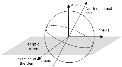
Figure 7.8 — Solar ecliptic ORM binding
NOTE The x-axis slowly rotates once per orbit of the planet around the Sun. The y-axis also lies in the ecliptic plane.
In the case of the Earth, the transformation from a solar ecliptic ORM embedding to the ORM WGS_1984 reference embedding is described in Annex B.
Table 7.22 is a directory of the Earth and other planet object solar ecliptic ORMs.
Table 7.22 — Solar ecliptic ORM directory
|
ORM label |
Published name |
|
Solar ecliptic |
|
|
Jupiter solar ecliptic |
7.5.4 Solar equatorial
A solar equatorial OBRS is specified in Table 7.23. See also Figure 7.9.
Table 7.23 — Solar equatorial OBRS
|
Element |
Value |
|
OBRS label |
|
|
OBRS code |
3 |
|
OBRS name |
solar equatorial |
|
Object restrictions |
A planet in the solar system for which the ecliptic plane is distinct from the equatorial plane. |
|
Object binding rules |
1) The RD ORIGIN_3D is the mass-centre of the planet. 2) The RD X_AXIS_3D is in the ecliptic plane and points in the direction of the Sun. 3) The RD Z_AXIS_3D is perpendicular to the RD X_AXIS_3D in the plane determined by the RD X_AXIS_3D and the rotational axis of the Sun and points northward. |
|
References |
[CRUS] |
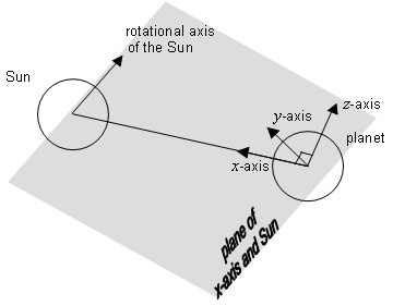
Figure 7.9 — Solar equatorial ORM binding
NOTE The xz-plane of a solar equatorial ORM contains the rotational axis of the Sun. The x-axis slowly rotates once per orbit of the object around the Sun. The y-axis is parallel to the solar equatorial plane and points towards dusk [BHAV, 3.2.6].
Table 7.24 is a directory of the Earth and other planet solar equatorial ORMs.
Table 7.24 — Solar equatorial ORM directory
|
ORM label |
Published name |
|
Solar equatorial |
|
|
Jupiter solar equatorial |
7.5.5 Heliocentric Aries ecliptic
The heliocentric Aries ecliptic OBRS is specified for a planet in Table 7.25. See [HAPG] and Figure 7.10.
Table 7.25 — Heliocentric Aries ecliptic OBRS
|
Element |
Value |
|
OBRS label |
|
|
OBRS code |
4 |
|
OBRS name |
heliocentric Aries ecliptic |
|
Object restrictions |
The Sun. |
|
Object binding rules |
1) The RD ORIGIN_3D is the mass-centre of the Sun. 2) The RD Z_AXIS_3D is perpendicular to the ecliptic plane of the Earth and points in the direction of rotational northwards. 3) The RD X_AXIS_3D is in the ecliptic plane of the Earth and points towards the first point of Aries. |
|
References |
[HAPG] |
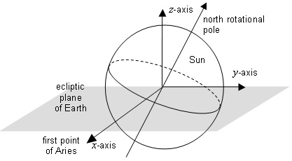
Figure 7.10 — Heliocentric Aries ecliptic ORM binding
See Figure 7.10. Table 7.26 is a directory of the Earth and other planet solar equatorial ORMs. The heliocentric Aries ecliptic axis directions are inertial for ORM HELIO_ARIES_ECLIPTIC_J2000r0 and quasi-inertial ORM HELIO_ARIES_ECLIPTIC_TRUE_OF_DATE.
Table 7.26 — Heliocentric Aries ecliptic ORM directory
|
ORM label |
Published name |
|
Heliocentric Aries ecliptic, J2000.0 |
|
|
Heliocentric Aries ecliptic, true of date |
7.5.6 Heliocentric planet ecliptic
The heliocentric planet ecliptic OBRS is specified for a planet in Table 7.27. See [HAPG] and Figure 7.11.
Table 7.27 — Heliocentric planet ecliptic OBRS
|
Element |
Value |
|
OBRS label |
|
|
OBRS code |
5 |
|
OBRS name |
heliocentric planet ecliptic |
|
Object restrictions |
The Sun. |
|
Object binding rules |
1) The RD ORIGIN_3D is the mass-centre of the Sun. 2) The RD Z_AXIS_3D is perpendicular to the ecliptic plane for a specified planet and points in the direction of rotational northwards. 3) The RD X_AXIS_3D is in the ecliptic plane of the specified planet and points towards the planet. |
|
References |
[HAPG] |
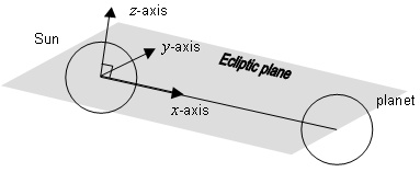
Figure 7.11 — Heliocentric planet ecliptic OBRS
Table 7.28 is a directory of the Earth and other planet solar equatorial ORMs.
Table 7.28 — Heliocentric planet ecliptic ORM directory
|
ORM label |
Published name |
|
Heliocentric Earth ecliptic |
7.5.7 Heliocentric planet equatorial
The heliocentric planet equatorial OBRS is specified for a planet in Table 7.29. See also Figure 7.12.
Table 7.29 — Heliocentric planet equatorial OBRS
|
Element |
Value |
|
OBRS label |
|
|
OBRS code |
6 |
|
OBRS name |
heliocentric planet equatorial |
|
Object restrictions |
The Sun. |
|
Object binding rules |
1) The RD ORIGIN_3D is the mass-centre of the Sun. 2) The RD Z_AXIS_3D is perpendicular to the solar equatorial plane of the specified planet and points in the direction of rotational northwards. 3) The RD X_AXIS_3D is perpendicular to the RD Z_AXIS_3D in the plane determined by the RD Z_AXIS_3D and the planet centre and points towards the specified planet. |
|
References |
[HAPG] |
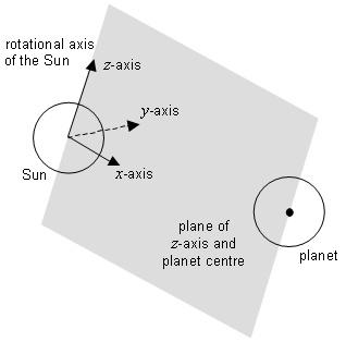
Figure 7.12 — Heliocentric planet equatorial OBRS
Table 7.30 is a directory of the Earth and other planet solar equatorial ORMs.
Table 7.30 — Heliocentric planet equatorial ORM directory
|
ORM label |
Published name |
|
Heliocentric Earth equatorial |
7.5.8 Celestiomagnetic
The celestiomagnetic OBRS is specified in Table 7.31. See [BHAV, 3.3.1] and Figure 7.13.
Table 7.31 — Celestiomagnetic OBRS
|
Element |
Value |
|
OBRS label |
|
|
OBRS code |
7 |
|
OBRS name |
celestiomagnetic |
|
Object restrictions |
A planet or rotating satellite in a solar system with a magnetic dipole axis distinct from its rotational axis. |
|
Object binding rules |
1) The RD ORIGIN_3D is the mass-centre of the planet. 2) The RD Z_AXIS_3D is parallel to the magnetic dipole axis and points towards magnetic north. 3) The RD X_AXIS_3D is contained in the plane through the origin that is parallel to the dipole and rotational axes, perpendicular to the RD Z_AXIS_3D and pointing away from the dipole northward direction. |
|
References |
[CRUS] |
NOTE The rotational south pole is contained in the x-positive xz-half-plane unless the planet has retrograde rotation. This binding is not applicable to Saturn whose magnetic and rotational poles are not distinguished.
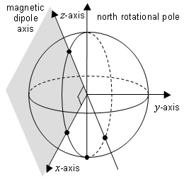
Figure 7.13 — Celestiomagnetic ORM binding
In the case of the Earth, this dynamic ERM is approximated as an Earth-fixed ERM for a five-year epoch. The other celestial objects that have observed magnetic dipoles have object-fixed ORM approximations for the corresponding dynamic ORMs.
Table 7.32 is a directory of the Earth and other object-fixed celestiomagnetic ORM approximations.
Table 7.32 — Celestiomagnetic ORM directory
|
ORM label |
Published name |
|
Ganymede magnetic |
|
|
Geomagnetic 1945 |
|
|
Geomagnetic 1950 |
|
|
Geomagnetic 1955 |
|
|
Geomagnetic 1960 |
|
|
Geomagnetic 1965 |
|
|
Geomagnetic 1970 |
|
|
Geomagnetic 1975 |
|
|
Geomagnetic 1980 |
|
|
Geomagnetic 1985 |
|
|
Geomagnetic 1990 |
|
|
Geomagnetic 1995 |
|
|
Geomagnetic 2000 |
7.5.9 Solar magnetic ecliptic
The solar magnetic ecliptic OBRS is specified in Table 7.33. See [BHAV, 3.3.4] and Figure 7.14.
Table 7.33 — Solar magnetic ecliptic OBRS
|
Element |
Value |
|
OBRS label |
|
|
OBRS code |
8 |
|
OBRS name |
solar magnetic ecliptic |
|
Object restrictions |
A planet in the solar system with a magnetic dipole. |
|
Object binding rules |
1) The RD ORIGIN_3D is the mass-centre of the planet. 2) The RD X_AXIS_3D is in the ecliptic plane of the planet pointing in the direction of the Sun. 3) The RD Z_AXIS_3D is perpendicular to the RD X_AXIS_3D and points in the direction of rotational northwards in the plane determined by the x-axis and the planetary magnetic dipole axis. |
|
References |
[CRUS] |
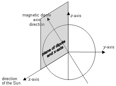
Figure 7.14 — Solar magnetic ecliptic ORM binding
Table 7.34 is a directory of the Earth and other planet solar magnetic ecliptic ORMs.
Table 7.34 — Solar magnetic ecliptic ORM directory
|
ORM label |
Published name |
|
Solar magnetospheric |
|
|
Jupiter solar magnetic ecliptic |
7.5.10 Solar magnetic dipole
The solar magnetic dipole OBRS is specified in Table 7.35. See [BHAV, 3.3.5] and Figure 7.15.
Table 7.35 — Solar magnetic dipole OBRS
|
Element |
Value |
|
OBRS label |
|
|
OBRS code |
9 |
|
OBRS name |
solar magnetic dipole |
|
Object restrictions |
A planet in the solar system with a magnetic dipole. |
|
Object binding rules |
1) The RD ORIGIN_3D is the mass-centre of the planet. 2) The RD Z_AXIS_3D is parallel to the planetary magnetic dipole axis and points towards magnetic north. 3) The RD X_AXIS_3D is perpendicular to the RD Z_AXIS_3D and pointing towards the Sun in the plane determined by the Sun and the RD Z_AXIS_3D. |
|
References |
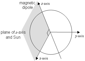
Figure 7.15 — Solar magnetic dipole ORM binding
Table 7.36 is a directory of the Earth and other celestial object solar magnetic dipole ORMs.
Table 7.36 — Solar magnetic dipole ORM directory
|
ORM label |
Published name |
|
Solar magnetic dipole |
|
|
Jupiter solar magnetic dipole |