8 Spatial reference frames
8.1 Introduction
A spatial coordinate system is a means of associating a unique coordinate with a point in object-space. It is defined by binding an abstract CS to a normal embedding (see 8.2). A spatial reference frame is a specification of a spatial coordinate system for a region of object-space (see 8.3). It is formed by the binding of an abstract coordinate system to the normal embedding specified by an ORM for that object. A full specification specifies the CS and the ORM and includes values for CS parameters, if any, and a specification of the region of object-space. Some or all CS parameters may be bound by ORM parameters. In particular, a CS based on an oblate ellipsoid (or sphere) must match the parameters of the oblate ellipsoid (or sphere) RD of the ORM.
A spatial reference frame template is an abstraction of a collection of spatial reference frames that share the same abstract coordinate system, coordinate system parameter binding rules, and similar ORMs that model the same spatial object type (see 8.5). Spatial reference frames may be organized into specified sets so as to form an atlas for a large region of space. This International Standard specifies a collection of spatial reference frame templates, realizations of those templates, and sets of those realizations.
8.2 Spatial coordinate systems
If a normal embedding of position-space into object-space is defined, any abstract CS for a region of that position-space can be used to specify a spatial CS that associates coordinates in coordinate-space to points in object-space. This association is a binding of a CS via a normal embedding. The association is defined as:

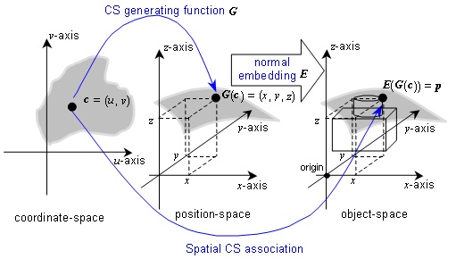
Figure 8.1 — A spatial embedding of a surface CS
EXAMPLE Figure 8.1 illustrates a spatial surface CS bound with a normal embedding of 3D position-space to the 3D object-space. In this illustration, a surface coordinate (u, v) in coordinate-space is associated to a position (x, y, z) in the abstract position-space. That position is then identified with a position in the space of an object via the normal embedding of position-space. In this example, the normal embedding is determined by the selection of an origin and three unit points.
8.3 Spatial reference frame
8.3.1 Specification
A spatial reference frame (SRF) is a specification of a spatial coordinate system that is constructed from an ORM and a compatible abstract CS, such that coordinates uniquely specify positions with respect to the spatial object of the ORM. A specification of an SRF includes:
a) an ORM,
b) a CS compatible with the ORM,
c) a binding of all parameters of the spatial CS,
d) (optionally) kth coordinate-component names,
e) (optionally) additional restrictions on the domain of valid coordinates in that spatial CS, and
f) (optionally) if the CS is of CS type 3D, a vertical coordinate-component identification (see 8.4).
An SRF implicitly specifies a spatial CS defined by the binding of the CS via the normal embedding associated with the ORM.
Spatial CS compatibility and the other elements of the specification of an SRF are defined in the following clauses.
8.3.2 SRF specification elements
8.3.2.1 ORM and CS compatibility
The compatible CS type of the CS element of an SRF depends on the dimension of the ORM. The dimension of an ORM is defined as the dimension of the RD components of the specification of the ORM. The compatible CS types by ORM dimension are specified in Table 8.1.
Table 8.1 — Compatible CS types
|
ORM dimension |
Compatible CS types |
|
1D |
1D CS |
|
2D |
Curve CS |
|
3D |
Curve CS |
The use of surface CSs or 3D CSs that are based on an oblate ellipsoid (or sphere) are restricted to ORMs that are based on an oblate ellipsoid (or respectively, sphere) RD.
The surface CSs that are based on an oblate ellipsoid (or sphere) are:
a) surface geodetic,
b) surface planetodetic, and
c) all map projections.
The 3D CSs that are based on an oblate ellipsoid (or sphere) are:
a) geodetic 3D, and
b) all augmented map projections.
As a further restriction, some CSs are based on spheres only. CS OBLIQUE_MERCATOR_SPHERICAL has this restriction.
8.3.2.2 CS parameter binding
All CS parameter values must be specified. In the case of a combination of a CS and an ORM based on an oblate ellipsoid (or sphere), the major semi-axis and minor semi-axis (or equivalently, the inverse flattening) (or respectively, sphere radius) of the ORM and CS shall match.
8.3.2.3 Coordinate-component names
A CS specification (see 5.9) includes the coordinate-component symbols with common names (if any). A specification of an SRF may optionally assign SRF-specific names to the kth coordinate-components. The name assignment shall reflect the common use in the intended application domain.
EXAMPLE For a spherical CS, the assignment of SRF-specific names to the kth coordinate-components of “right ascension” for λ, “declination” for θ , and “radius” for ρ.
8.3.2.4 Coordinate valid-region
A CS specification (see 5.9) includes the specification of the CS domain and CS range where the generating function (or mapping equations) and its inverse(s) are defined. An SRF specification may further restrict the CS domain. A valid-region is a restriction of the CS domain of the generating function (or mapping equations) for a CS as used in an SRF. An extended valid-region is a second valid-region that contains the first valid-region as a subset. The specification of these restrictions is important for several (SRF specific) reasons:
a) If the ORM is local, the restrictions are used to model, in coordinate-space, the local region of the space of the object.
b) If the CS is a map projection or an augmented map projection, the restrictions are used to bound or otherwise limit distortions (see 5.8.3.1).
c) The SRF may be used in conjunction with other SRFs to form an atlas for a large region (see 8.7 SRF sets). In this case, the restrictions are used to control the pair-wise overlap of the spatial coverage of members of the SRF collection.
d) If the CS generating function (or map projection mapping equations) or the inverse function(s) have been implemented with a numerical approximation, the restrictions are used to control error bounds.
The extended valid-region is used primarily for overlapping regions in forming an atlas as in (c) above. Not all properties of the SRF that are true in the valid-region will necessarily be true in the extended valid-region. In particular, a distortion error bound that holds in the valid-region may not hold in the extended valid-region.
A valid-region may be described and/or specified. A valid-region description is a descriptive statement of the region such as the spatial boundary of a named political entity.
EXAMPLE 1 “The German state of Baden-Wurttemberg” and “The Baltic Sea” are valid-region descriptions.
In this International Standard, a valid-region specification is a finite (or empty) list of coordinate-component constraints of the form:
kth coordinate-component belongs to a non-empty interval of real
numbers![]() .
.
An extended valid-region specification is a finite (or empty) list of coordinate-component constraints of the form:
kth coordinate-component belongs to an interval of real numbers![]() , where
, where ![]() has been
specified and
has been
specified and![]() .
.
Angular coordinate-component intervals
shall be evaluated modulo 2p to represent an interval of the unit circle. Thus, ![]()
In the case of an SRF with an oblate
ellipsoid (or sphere) based ORM,
celestiodetic coordinates may be similarly constrained. In particular,
valid-region specifications for a map projection based SRF may specify
coordinate-component constraints for easting, northing, latitude, and/or
longitude. Celestiodetic longitude intervals shall be evaluated modulo 2π. In particular, if the interval limits satisfy![]() , then:
, then:

EXAMPLE 2 The SRF is based on a transverse Mercator map projection (see SRFT TRANSVERSE_MERCATOR).
Valid-region specification: 0 ≤ u ≤ 10 000 000, 0
≤ v ≤ 500
000
Extended valid-region specification: -100 < u, -100
< v
In this example, ![]() and
and ![]() are closed bounded intervals,
and
are closed bounded intervals,
and ![]() and
and ![]() are open semi-bounded
intervals.
are open semi-bounded
intervals.
EXAMPLE 3 The SRF is based on a transverse Mercator map projection (see SRFT TRANSVERSE_MERCATOR).
Valid-region specification: -78º
≤ λ < -72º, 0º ≤ θ < 84º
Extended valid-region specification: -78,5º ≤ λ <
-71,5º
In this example, ![]() and
and ![]() are left-closed, right-open
bounded intervals, as is
are left-closed, right-open
bounded intervals, as is ![]() .
.
![]() is not specified. This
indicates that there are no constraints for latitude (except for the CS domain
definition) in the extended valid-region specification.
is not specified. This
indicates that there are no constraints for latitude (except for the CS domain
definition) in the extended valid-region specification.
8.4 SRF induced surface spatial reference frame
In the case of an SRF specified with the combination of a 3D ORM and a 3D CS, the 3D CS induces a surface CS on each coordinate-component surface (see 5.5.2). An SRF specification may optionally identify the 3rd coordinate-component as the vertical coordinate-component for the SRF. In that case, the surface CS induced on the zero-value vertical coordinate-component surface is the induced surface SRF for the specification. The vertical coordinate-component is optionally specified in the coordinate-component name specification element of the SRF.
The CS GEODETIC and the CS PLANETODETIC 3rd coordinate-components (h: ellipsoidal height), and the 3rd coordinate-component of any augmented map projection CS (h: ellipsoidal height) are identified in this International Standard as the vertical coordinate-component. When an SRF is specified with any of these 3D CSs, the h = 0 coordinate-component surface coincides with the surface of the oblate ellipsoid (or sphere) RD of the ORM. Any SRF based on these CSs intrinsically specifies the corresponding surface CS on the oblate ellipsoid (or sphere) RD surface.
An SRF realized from the SRF template LOCAL_TANGENT_SPACE_EUCLIDEAN specification (see 8.5.6) or the SRF template LOCAL_TANGENT_SPACE_CYLINDRICAL specification (see 8.5.8), the 3rd coordinate-component, height, is specified as the vertical coordinate-component. In these cases, the zero-value vertical coordinate-component surface is a plane that is tangent to the oblate ellipsoid (or sphere) RD of the ORM. SRF templates are defined in 8.5.
The zero-value 3rd coordinate-component surface of an SRF realized from the 3D CS SRF template LOCAL_TANGENT_SPACE_AZIMUTHAL_SPHERICAL specification (see 8.5.7) induces a lococentric surface azimuthal CS on the tangent plane of the SRF. For the purpose of specifying an induced surface reference frame, the 3rd coordinate-component q, depression/elevation angle, is specified as a vertical coordinate. The zero-value vertical coordinate-component surface is a plane that is tangent to the oblate ellipsoid (or sphere) RD of the ORM.
SRF templates that are based on surface CSs that can be induced by a zero-value vertical coordinate-component surface of an SRF based on a 3D CS are not separately specified. The induced surface CS is noted in the corresponding 3D CS based SRF template specification.
NOTE Starting with a 3D SRF, this International Standard identifies surface SRFs on coordinate-component surfaces. The relationship between a surface CS and the 3D CS which induces it is functionally similar to, but conceptually different from, the ISO 19111 concept of compound coordinate reference frame. A compound coordinate reference frame synthesizes a 3D reference frame from a surface and a vertical system. (See also 5.8.6.1 and Clause 9.)
8.5 SRF templates
8.5.1 Introduction
An spatial reference frame template (SRFT) is an abstraction of a collection of SRFs that share the same abstract CS, coordinate component names, CS parameter binding rules, and similar ORMs that model the same spatial object type. An SRF template allows for a consistent derivation of SRFs. It is not necessary that an appropriate SRFT be defined in order to define a new SRF; however in this International Standard all SRFs are derived from SRFTs. The specification elements for SRFTs are defined in Table 8.2.
Table 8.2 — SRFT specification elements
|
Element |
Definition |
|
SRFT label |
The label of the SRF template (see 13.2.2). |
|
SRFT code |
The code of the SRF template (see 13.2.3). |
|
Short name and description |
A short name as published or as commonly known and an optional description. |
|
Object or object type |
One or more of: abstract, physical, Earth, planet, satellite, and Sun; and, optionally, additional restrictions. |
|
ORM constraint |
Criteria for allowable ORMs. |
|
CS label |
The label of a CS of compatible type. |
|
CS coordinate-component names and/or symbols |
SRF-specific names and/or symbols for the kth coordinate-component names and/or symbols. If all coordinate-component names and symbols are the same as the CS, the phrase “Same as the CS.” shall be used. The vertical coordinate-component shall be designated in this specification element if applicable. |
|
Template parameters |
CS and RD parameters, if any, and/or SRF parameters that are not specified by a CS parameter binding rule. |
|
CS parameter binding rules |
A set of rules for binding for CS parameters and ORM component RD parameters, if any, and/or SRF parameters. |
|
Coordinate valid-region |
Optional restriction of the domain of the CS to a valid-region. If a valid-region is specified, optionally an extended valid-region. If both are unspecified, then there are no additional constraints on coordinate validity. |
|
Notes |
Optional, additional, non-normative information such as a description of the SRF structure, modelled region, intended use, and/or application domain. |
|
References |
The references (see 13.2.5). |
This International Standard specifies a collection of SRFTs as identified in Table 8.3. Additional SRFTs may be registered in accordance with Clause 13. Registered SRFs shall be derived only from standardized or registered SRFTs.
|
CS type |
Short name |
SRFT label |
|
3D |
Celestiocentric |
|
|
Local space rectangular 3D |
||
|
Celestiodetic |
||
|
Planetodetic |
||
|
Local tangent space Euclidean |
||
|
Local tangent space azimuthal spherical |
||
|
Local tangent space cylindrical |
||
|
Lococentric Euclidean 3D |
||
|
Celestiomagnetic |
||
|
Equatorial inertial |
||
|
Solar ecliptic |
||
|
Solar equatorial |
||
|
Solar magnetic ecliptic |
||
|
Solar magnetic |
||
|
Heliospheric Aries ecliptic |
||
|
Heliospheric Earth ecliptic |
||
|
Heliospheric Earth equatorial |
||
|
Surface (map projection) and 3D (augmented map projection) |
Mercator |
|
|
Oblique Mercator spherical |
||
|
Transverse Mercator |
||
|
Lambert conformal conic |
||
|
Polar stereographic |
||
|
Equidistant cylindrical |
||
|
Surface |
Surface celestiodetic (induced) |
|
|
Surface planetodetic (induced) |
||
|
Local tangent plane Euclidean (induced) |
||
|
Local tangent plane azimuthal (induced) |
||
|
Local tangent plane polar (induced) |
||
|
2D |
Local space rectangular 2D |
|
|
Local space azimuthal |
||
|
Local space polar |
8.5.2 Celestiocentric SRFT
Celestiocentric SRFs shall be derived from the SRFT specified in Table 8.4.
Table 8.4 — Celestiocentric SRFT
|
Element |
Specification |
|
SRFT label |
|
|
SRFT code |
1 |
|
Short name and description |
celestiocentric SRFT |
|
Object type |
physical |
|
ORM constraint |
Shall be derived from any 3D ORM. |
|
CS label |
|
|
CS
coordinate-component |
The same as the CS. |
|
Template parameters |
none |
|
CS parameter binding rules |
None (no CS parameters). |
|
Coordinate valid-region |
No additional restrictions. |
|
Notes |
When the object is Earth, this SRFT is referred to as a geocentric SRFT. |
|
References |
[EDM] |
8.5.3 Local space rectangular 3D SRFT
Local space rectangular SRFs shall be derived from the SRFT specified in Table 8.5.
Table 8.5 — Local space rectangular 3D SRFT
|
Element |
Specification |
|
|
SRFT label |
||
|
SRFT code |
2 |
|
|
Short name and description |
local space rectangular
3D SRFT |
|
|
Object type |
3D abstract object. |
|
|
ORM constraint |
Shall be an ORM for a 3D abstract object. |
|
|
CS label |
||
|
CS
coordinate-component |
The same as the CS. |
|
|
Template parameters |
r = vector direction of forward
(forward axis). |
|
|
CS parameter binding rules |
|
|
|
Coordinate valid-region |
No additional restrictions. |
|
|
Notes |
||
|
References |
[EDM] |
|

8.5.4 Celestiodetic SRFT
Celestiodetic SRFs shall be derived from the SRFT specified in Table 8.6.
Table 8.6 — Celestiodetic SRFT
|
Element |
Specification |
|
SRFT label |
|
|
SRFT code |
3 |
|
Short name and description |
celestiodetic SRFT |
|
Object type |
physical |
|
ORM constraint |
Shall be derived from: |
|
CS label |
|
|
CS coordinate-component names and/or symbols |
The same as the CS. |
|
Template parameters |
none |
|
CS parameter binding rules |
CS parameters match RD values. |
|
Coordinate valid-region |
No additional restrictions. |
|
Notes |
1) The SURFACE_GEODETIC CS is induced on the oblate ellipsoid (or sphere) RD surface. 2) When the object is Earth, this SRFT is referred to as a geodetic SRFT. |
|
References |
[HEIK] |
8.5.5 Planetodetic SRFT
Planetodetic SRFs shall be derived from the SRFT specified in Table 8.7.
|
Element |
Specification |
|
SRFT label |
|
|
SRFT code |
4 |
|
Short name and description |
planetodetic SRFT |
|
Object type |
planet |
|
ORM constraint |
Shall be derived from: |
|
CS label |
|
|
CS coordinate names and/or symbols |
The same as the CS. |
|
Template parameters |
none |
|
CS parameter binding rules |
CS parameters match RD values: |
|
Coordinate valid region |
No additional restrictions |
|
Notes |
Planetary science applications |
|
References |
[RIIC] |
8.5.6 Local tangent space Euclidean SRFT
Local tangent space Euclidean SRFs shall be derived from the SRFT specified in Table 8.8. The case with template parameters a = 0 and h0 = 0 is illustrated in Figure 8.2.
Table 8.8 — Local tangent space Euclidean SRFT
|
Element |
Specification |
|
SRFT label |
|
|
SRFT code |
5 |
|
Short name and description |
local
tangent space Euclidean SRFT |
|
Object type |
physical |
|
ORM constraint |
Shall be derived from: |
|
CS label |
|
|
CS coordinate-component names and/or symbols |
u: x
(x) |
|
Template parameters |
|
|
CS parameter binding rules |
|
|
Coordinate valid-region |
No additional restrictions. |
|
Notes |
1) The LOCOCENTRIC_SURFACE_EUCLIDEAN CS is induced on the tangent plane surface. 2) The w = -h0 coordinate-component plane21 is tangent to the oblate ellipsoid RD at the point with surface celestiodetic coordinate (λ,φ). 3) α is the geodetic azimuth of the v-axis (see Figure 8.2). 4) h0 is the ellipsoidal height of the CS origin. |
|
References |
[EDM] |


Figure 8.2 — Local tangent space Euclidean SRFT
8.5.7 Local tangent space azimuthal spherical SRFT
Local tangent space azimuthal spherical SRFs shall be derived from the SRFT specified in Table 8.9.
Table 8.9 — Local tangent space azimuthal spherical SRFT
|
Element |
Specification |
|
SRFT label |
|
|
SRFT code |
6 |
|
Short name and description |
local tangent space
azimuthal spherical SRFT |
|
Object type |
physical |
|
ORM constraint |
Shall be derived from: |
|
CS label |
|
|
CS
coordinate-component |
The same as the CS. θ: depression/elevation angle, is the vertical coordinate-component. |
|
Template parameters |
|
|
CS parameter binding rules |
|
|
Coordinate valid-region |
No additional restrictions. |
|
Notes |
1) Used in radar localization. 2) h0 is the ellipsoidal height of the CS origin. 3) α is the geodetic azimuth of the v-axis (see Figure 8.2). |
|
References |
[EDM] |


8.5.8 Local tangent space cylindrical SRFT
Local tangent space cylindrical SRFs shall be derived from the SRFT specified in Table 8.10.
Table 8.10 — Local tangent space cylindrical SRFT
|
Element |
Specification |
|
SRFT label |
LOCAL_TANGENT_SPACE_CYLINDRICAL |
|
SRFT code |
7 |
|
Short name and description |
local tangent space
cylindrical SRFT |
|
Object type |
physical |
|
ORM constraint |
Shall be derived from: |
|
CS label |
|
|
CS
coordinate-component |
|
|
Template parameters |
|
|
CS parameter binding rules |
|
|
Coordinate valid-region |
No additional restrictions. |
|
Notes |
1) The LOCOCENTRIC_SURFACE_POLAR CS is induced on the tangent plane surface. 2) The w = -h0 coordinate-component plane21 is tangent to the oblate ellipsoid RD at the point with surface celestiodetic coordinate (λ,φ). 3) α is the geodetic azimuth of the v-axis (see Figure 8.2). 4) h0 is the ellipsoidal height of the CS origin. |
|
References |
[EDM] |


8.5.9 Lococentric Euclidean 3D SRFT
Lococentric Euclidean 3D SRFs shall be derived from the SRFT specified in Table 8.11.
Table 8.11 — Lococentric Euclidean 3D SRFT
|
Element |
Specification |
|
SRFT label |
|
|
SRFT code |
8 |
|
Short name and description |
Lococentric
Euclidean 3D SRFT |
|
Object type |
Any 3D object |
|
ORM constraint |
Shall be derived from any 3D ORM. |
|
CS label |
|
|
CS coordinate-component names and/or symbols |
The same as the CS. |
|
Template parameters |
Localization parameters: q: the lococentric origin, Constraints: |
|
CS parameter binding rules |
The template parameters are the CS parameters |
|
Coordinate valid-region |
No additional restrictions. |
|
Notes |
1) A CELESTIOCENTRIC SRFT is
special case of an instance of this SRFT with 2) A LOCAL_SPACE_RECTANGULAR_3D
SRFT is special case of an instance of this SRFT with 3) A LOCAL_TANGENT_SPACE_EUCLIDEAN SRFT is special case of an instance of this SRFT with q, r, s, satisfying the SRFT LOCAL_TANGENT_SPACE_EUCLIDEAN CS parameter binding rules and ORM constraint. 4) This SRTF is required for the SRM treatment of directions (see 10.5) |
|
References |
[EDM] |
8.5.10 Celestiomagnetic SRFT
Celestiomagnetic SRFs shall be derived from the SRFT specified in Table 8.12.
Table 8.12 — Celestiomagnetic SRFT
|
Element |
Specification |
|
SRFT label |
|
|
SRFT code |
9 |
|
Short name and description |
celestiomagnetic SRFT |
|
Object type |
A planet or rotating satellite in a solar system with a magnetic dipole axis distinct from its rotational axis. |
|
ORM constraint |
Based on ORMT BI_AXIS_ORIGIN_3D and OBRS celestiomagnetic. |
|
CS label |
|
|
CS
coordinate-component |
The same as the CS. |
|
Template parameters |
none |
|
CS parameter binding rules |
none |
|
Coordinate valid-region |
No additional restrictions. |
|
Notes |
1) See 7.5.8. 2) When the object is Earth, this SRFT is referred to as a geomagnetic SRFT. 3) These SRFs are typically used at radii where the magnetic field is approximated by a dipole. |
|
References |
[CRUS] |
8.5.11 Equatorial inertial SRFT
Equatorial inertial SRFs shall be derived from the SRFT specified in Table 8.13.
Table 8.13 — Equatorial inertial SRFT
|
Element |
Specification |
|
SRFT label |
|
|
SRFT code |
10 |
|
Short name and description |
equatorial Inertial SRFT |
|
Object type |
A planet in the solar system for which the ecliptic plane is distinct from the equatorial plane. |
|
ORM constraint |
Based on ORMT BI_AXIS_ORIGIN_3D and OBRS equatorial_inertial. |
|
CS label |
|
|
CS
coordinate-component |
λ : right ascension (ra) |
|
Template parameters |
none |
|
CS parameter binding rules |
none |
|
Coordinate valid-region |
No additional restrictions. |
|
Notes |
1) See 7.5.2. 2) Star catalogues use right ascension and declination to specify directions. |
|
References |
[SEID] |
8.5.12 Solar ecliptic SRFT
Solar ecliptic SRFs shall be derived from the SRFT specified in Table 8.14.
Table 8.14 — Solar ecliptic SRFT
|
Element |
Specification |
|
SRFT label |
|
|
SRFT code |
11 |
|
Short name and description |
solar ecliptic SRFT |
|
Object type |
A planet in the solar system. |
|
ORM constraint |
Based on ORMT BI_AXIS_ORIGIN_3D and OBRS solar_ecliptic. |
|
CS label |
|
|
CS
coordinate-component |
The same as the CS. |
|
Template parameters |
none |
|
CS parameter binding rules |
none |
|
Coordinate valid-region |
No additional restrictions. |
|
Notes |
See 7.5.3. |
|
References |
[HAPG] |
8.5.13 Solar equatorial SRFT
Solar equatorial SRFs shall be derived from the SRFT specified in Table 8.15.
Table 8.15 — Solar equatorial SRFT
|
Element |
Specification |
|
SRFT label |
|
|
SRFT code |
12 |
|
Short name and description |
solar equatorial SRFT |
|
Object type |
A planet in the solar system for which the ecliptic plane is distinct from the equatorial plane. |
|
ORM constraint |
Based on ORMT BI_AXIS_ORIGIN_3D and OBRS SOLAR_EQUATORIAL. |
|
CS label |
|
|
CS
coordinate-component |
The same as the CS. |
|
Template parameters |
none |
|
CS parameter binding rules |
none |
|
Coordinate valid-region |
No additional restrictions. |
|
Notes |
See 7.5.4. |
|
References |
[CRUS] |
8.5.14 Solar magnetic ecliptic SRFT
Solar magnetic ecliptic SRFs shall be derived from the SRFT specified in Table 8.16.
Table 8.16 — Solar magnetic ecliptic SRFT
|
Element |
Specification |
|
SRFT label |
SOLAR_MAGNETIC_ECLIPTIC |
|
SRFT code |
13 |
|
Short name and description |
solar magnetic ecliptic SRFT |
|
Object type |
A planet in the solar system with a magnetic dipole. |
|
ORM constraint |
Based on ORMT BI_AXIS_ORIGIN_3D and OBRS SOLAR_MAGNETIC_ECLIPTIC. |
|
CS label |
|
|
CS
coordinate-component |
The same as the CS. |
|
Template parameters |
none |
|
CS parameter binding rules |
none |
|
Coordinate valid-region |
No additional restrictions. |
|
Notes |
1) See 7.5.9. 2) In the case of planet Earth, this STF is also known as a geocentric solar magnetospheric SRF. |
|
References |
[CRUS] |
8.5.15 Solar magnetic dipole SRFT
Solar magnetic dipole SRFs shall be derived from the SRFT specified in Table 8.17.
Table 8.17 — Solar magnetic dipole SRFT
|
Element |
Specification |
|
SRFT label |
SOLAR_MAGNETIC_DIPOLE |
|
SRFT code |
14 |
|
Short name and description |
solar magnetic dipole SRFT |
|
Object type |
A planet in the solar system with a magnetic dipole axis distinct from its rotational axis. |
|
ORM constraint |
Based on ORMT BI_AXIS_ORIGIN_3D and OBRS SOLAR_MAGNETIC_DIPOLE. |
|
CS label |
|
|
CS
coordinate-component |
The same as the CS. |
|
Template parameters |
none |
|
CS parameter binding rules |
none |
|
Coordinate valid-region |
No additional restrictions. |
|
Notes |
See 7.5.10. |
|
References |
8.5.16 Heliospheric Aries ecliptic SRFT
Heliospheric Aries ecliptic SRFs shall be derived from the SRFT specified in Table 8.18.
Table 8.18 — Heliospheric Aries ecliptic SRFT
|
Element |
Specification |
|
SRFT label |
|
|
SRFT code |
15 |
|
Short name and description |
Heliospheric Aries
ecliptic SRFT |
|
Object type |
Sun. |
|
ORM constraint |
Based on ORMT BI_AXIS_ORIGIN_3D and OBRS heliocentric_ARIES_ecliptic. |
|
CS label |
|
|
CS
coordinate-component |
The same as the CS. |
|
Template parameters |
none |
|
CS parameter binding rules |
none |
|
Coordinate valid-region |
No additional restrictions. |
|
Notes |
See 7.5.5. |
|
References |
[HAPG] |
8.5.17 Heliospheric Earth ecliptic SRFT
Heliospheric Earth ecliptic SRFs shall be derived from the SRFT specified in Table 8.19.
Table 8.19 — Heliospheric Earth ecliptic SRFT
|
Element |
Specification |
|
SRFT label |
|
|
SRFT code |
16 |
|
Short name and description |
heliospheric Earth
ecliptic SRFT |
|
Object type |
Sun. |
|
ORM constraint |
Based on ORMT BI_AXIS_ORIGIN_3D and OBRS Heliocentric_Planet_Ecliptic. |
|
CS label |
|
|
CS
coordinate-component |
The same as the CS. |
|
Template parameters |
none |
|
CS parameter binding rules |
none |
|
Coordinate valid-region |
No additional restrictions. |
|
Notes |
See 7.5.6. |
|
References |
[HAPG] |
8.5.18 Heliospheric Earth equatorial SRFT
Heliospheric Earth equatorial SRFs shall be derived from the SRFT specified in Table 8.20.
Table 8.20 — Heliospheric Earth equatorial SRFT
|
Element |
Specification |
|
SRFT label |
|
|
SRFT code |
17 |
|
Short name and description |
heliospheric Earth
equatorial SRFT |
|
Object type |
Sun. |
|
ORM constraint |
Based on ORMT BI_AXIS_ORIGIN_3D and OBRS Heliocentric_Planet_Equatorial with respect to Earth. |
|
CS label |
|
|
CS
coordinate-component |
The same as the CS. |
|
Template parameters |
none |
|
CS parameter binding rules |
none |
|
Coordinate valid-region |
No additional restrictions. |
|
Notes |
See 7.5.7. |
|
References |
[HAPG] |
8.5.19 Mercator SRFT
Mercator SRFs shall be derived from the SRFT specified in Table 8.21.
|
Element |
Specification |
|
SRFT label |
|
|
SRFT code |
18 |
|
Short name and description |
Mercator SRFT. |
|
Object type |
physical |
|
ORM constraint |
Shall be derived from: |
|
CS label |
|
|
CS
coordinate-component |
Same as the CS. |
|
Template parameters |
|
|
CS parameter binding rules |
CS parameters match RD
values: |
|
Coordinate valid-region |
No additional restrictions. |
|
Notes |
1. The augmented Mercator CS induces the Mercator CS on the zero-value vertical coordinate-component surface (which coincides with the RD surface). 2. True scale (point distortion = 1) may be specified at a given
latitude |
|
References |
[SNYD] |

8.5.20 Oblique Mercator spherical SRFT
Oblique Mercator spherical SRFs shall be derived from the SRFT specified in Table 8.22.
Table 8.22 — Oblique Mercator spherical SRFT
|
Element |
Specification |
|
SRFT label |
OBLIQUE_MERCATOR_SPHERICAL |
|
SRFT code |
19 |
|
Short name and description |
Oblique Mercator SRFT
for a sphere ORM. |
|
Object type |
physical |
|
ORM constraint |
Shall be derived from ORMT SPHERE. |
|
CS label |
|
|
CS
coordinate-component |
Same as the CS. |
|
Template parameters |
|
|
CS parameter binding rules |
The CS parameter R matches the RD value:
|
|
Coordinate valid-region |
No additional restrictions. |
|
Notes |
The augmented oblique Mercator CS induces the oblique Mercator CS on the zero-value vertical coordinate-component surface (which coincides with the RD surface). |
|
References |
[SNYD] |


8.5.21 Transverse Mercator SRFT
Transverse Mercator SRFs shall be derived from the SRFT specified in Table 8.23.
Table 8.23 — Transverse Mercator SRFT
|
Element |
Specification |
|
SRFT label |
|
|
SRFT code |
20 |
|
Short name and description |
Transverse Mercator SRFT |
|
Object type |
physical |
|
ORM constraint |
Shall be derived from: |
|
CS label |
|
|
CS
coordinate-component |
Same as the CS. |
|
Template parameters |
|
|
CS parameter binding rules |
CS parameters match RD
values: |
|
Coordinate valid-region |
No additional restrictions. |
|
Notes |
The augmented transverse Mercator CS induces the transverse Mercator CS on the zero-value vertical coordinate-component surface (which coincides with the RD surface). |
|
References |
[SNYD] |

8.5.22 Lambert conformal conic SRFT
Lambert conformal conic SRFs shall be derived from the SRFT specified in Table 8.24.
Table 8.24 — Lambert conformal conic SRFT
|
Element |
Specification |
|
SRFT label |
|
|
SRFT code |
21 |
|
Short name and description |
Lambert conformal conic SRFT |
|
Object type |
physical |
|
ORM constraint |
Shall be derived from: |
|
CS label |
|
|
CS
coordinate-component |
Same as the CS. |
|
Template parameters |
|
|
CS parameter binding rules |
CS parameters match RD
values: |
|
Coordinate valid-region |
No additional restrictions. |
|
Notes |
The augmented Lambert conformal conic CS induces the Lambert conformal conic CS on the zero-value vertical coordinate-component surface (which coincides with the RD surface). |
|
References |
[SNYD] |

8.5.23 Polar stereographic SRFT
Polar stereographic SRFs shall be derived from the SRFT specified in Table 8.25.
Table 8.25 — Polar stereographic SRFT
|
Element |
Specification |
|
SRFT label |
|
|
SRFT code |
22 |
|
Short name and description |
Polar stereographic SRFT |
|
Object type |
physical |
|
ORM constraint |
Shall be derived from: |
|
CS label |
|
|
CS
coordinate-component |
Same as the CS. |
|
Template parameters |
|
|
CS parameter binding rules |
CS parameters match RD
values:
|
|
Coordinate valid-region |
No additional restrictions. |
|
Notes |
1. The augmented polar stereographic CS induces the polar stereographic CS on the zero-value vertical coordinate-component surface (which coincides with the RD surface). 2. True scale (point distortion = 1) may be specified at a given latitude
|
|
References |
[SNYD] |


8.5.24 Equidistant cylindrical SRFT
Equidistant cylindrical SRFs shall be derived from the SRFT specified in Table 8.26.
Table 8.26 — Equidistant cylindrical SRFT
|
Element |
Specification |
|
SRFT label |
|
|
SRFT code |
23 |
|
Short name and description |
equidistant cylindrical SRFT |
|
Object type |
physical |
|
ORM constraint |
Shall be derived from ORMT OBLATE_ELLIPSOID
or |
|
CS label |
|
|
CS
coordinate-component |
Same as the CS. |
|
Template parameters |
|
|
CS parameter binding rules |
CS parameters match RD
values: |
|
Coordinate valid-region |
No additional restrictions. |
|
Notes |
1. The augmented equidistant cylindrical CS induces the equidistant cylindrical CS on the zero-value vertical coordinate-component surface (which coincides with the RD surface). 2. Longitudinal point distortion may be set to one at a given
latitude |
|
References |
[SNYD] |

8.5.25 Local space rectangular 2D SRFT
Local space rectangular 2D SRFs shall be derived from the SRFT specified in Table 8.27.
Table 8.27 — Local space rectangular 2D SRFT
|
Element |
Specification |
|
SRFT label |
|
|
SRFT code |
24 |
|
Short name and description |
local space rectangular
2D SRFT |
|
Object type |
2D abstract object |
|
ORM constraint |
Shall be an ORM for a 2D abstract object. |
|
CS label |
|
|
CS
coordinate-component |
The same as the CS. |
|
Template parameters |
r = vector direction of forward (forward axis). |
|
CS parameter binding rules |
|
|
Coordinate valid-region |
No additional restrictions. |
|
Notes |
|
|
References |
[EDM] |


8.5.26 Local Space azimuthal 2D SRFT
Azimuthal 2D SRFs shall be derived from the SRFT specified in Table 8.28.
Table 8.28 — Local Space azimuthal 2D SRFT
|
Element |
Specification |
|
SRFT label |
|
|
SRFT code |
25 |
|
Short name and description |
Local space azimuthal 2D
SRFT |
|
Object type |
Abstract object |
|
ORM constraint |
Shall be an ORM for a 2D abstract object. |
|
CS label |
|
|
CS
coordinate-component |
The same as the CS. |
|
Template parameters |
none |
|
CS parameter binding rules |
none |
|
Coordinate valid-region |
No additional restrictions. |
|
Notes |
none |
|
References |
[EDM] |
8.5.27 Local space Polar 2D SRFT
Polar 2D SRFs shall be derived from the SRFT specified in Table 8.29.
Table 8.29 — Local space Polar 2D SRFT
|
Element |
Specification |
|
SRFT label |
|
|
SRFT code |
26 |
|
Short name and description |
Local space polar 2D SRFT |
|
Object type |
Abstract object |
|
ORM constraint |
Shall be an ORM for a 2D abstract object. |
|
CS label |
|
|
CS
coordinate-component |
The same as the CS. |
|
Template parameters |
none |
|
CS parameter binding rules |
none |
|
Coordinate valid-region |
No additional restrictions. |
|
Notes |
none |
|
References |
[EDM] |
8.6 Standardized SRFs
This International Standard specifies a collection of SRFs. These specifications appear in Table 8.32 through Table 8.45. Table 8.31 is a directory of these specifications. These SRFs are each derived from a SRFT. Additional SRFs derived from SRFTs may be registered in accordance with Clause 13.
8.6.1 Introduction
The specification elements for SRFs are defined in Table 8.30.
Table 8.30 — Standardized SRF specification elements
|
Element |
Definition |
|
SRF label |
The label of the SRF (see 13.2.2). |
|
SRF code |
The code of the SRF (see 13.2.3). |
|
Short name |
A short name as published or as commonly known and an optional description. |
|
SRF template |
The label of the applicable SRF template. |
|
ORM |
The label of the applicable ORM. |
|
Valid-region |
Optional restriction of the domain of the CS to a valid-region description and/or a valid-region specification. If a valid-region is specified, optionally, an extended valid-region may be specified. Valid-region specifications and extended valid-region specifications are specified by value or by reference. Terms appearing in the references that are cited for a value shall be enclosed in brackets ( { } ). |
|
Parameter values |
The SRF template parameter values specified by value or by reference. If by reference, this specification element shall contain a citation(s) for the SRF template parameters values. Terms appearing in the references that are cited for a value shall be enclosed in brackets ( { } ). Any parameter value that is not specified in the citation(s) shall be specified by value. |
|
Notes |
Optional, additional, non-normative information concerning the SRF, such as a description of its structure, modelled region, intended use, and/or application domain. |
|
References |
The references (see 13.2.5). |
Table 8.31 — Directory of standardized SRFs
|
Short name |
SRF label |
|
British national grid |
|
|
UK ordnance survey GRS80 grid. |
|
|
Delaware (US) state plane coordinate system |
|
|
Geocentric WGS 1984 |
|
|
Geodetic Australia 1984 |
|
|
Geodetic WGS 1984 |
|
|
Geodetic north american 1983 |
|
|
Irish grid |
|
|
Irish transverse Mercator |
|
|
Lambert-93 |
|
|
Lambert II étendu (Lambert II wide) |
|
|
Mars planetocentric |
|
|
Mars planetodetic |
|
|
Maryland (US) state plane coordinate system |
8.6.2 British national grid
Table 8.32 — British national grid SRF
|
Element |
Specification |
Element |
Specification |
|
SRF label |
SRF code |
1 |
|
|
Short name |
British national grid. A transverse Mercator projection using the AIRY_1830 ellipsoid. |
||
|
SRF template |
ORM |
||
|
Valid-region |
Valid-region description: |
||
|
Parameter values |
longitude of
origin: λorigin = -2º |
||
|
Notes |
Also known as the UK national projection. |
||
|
References |
[OSTM, Section 7, "National projection"] |
||
8.6.3 UK ordnance survey GRS80 grid
Table 8.33 — UK ordnance survey GRS80 grid SRF
|
Element |
Specification |
Element |
Specification |
|
SRF label |
SRF code |
2 |
|
|
Short name |
UK ordnance survey GRS80 grid. A transverse Mercator projection using the GRS_1980 ellipsoid. |
||
|
SRF template |
ORM |
||
|
Valid-region |
Valid-region description: |
||
|
Parameter values |
longitude of
origin: λorigin = -2º |
||
|
Notes |
Also known as the OSGRS80 grid. |
||
|
References |
[OSTM, Section 7, " OSGRS80"] |
||
8.6.4 Delaware (US) state plane coordinate system
Table 8.34 — Delaware (US) state plane coordinate system SRF
|
Element |
Specification |
Element |
Specification |
|
SRF label |
SRF code |
3 |
|
|
Short name |
Delaware (US) state plane coordinate system |
||
|
SRF template |
ORM |
||
|
Valid-region |
Valid-region description: |
||
|
Parameter values |
longitude of
origin: λorigin = -75º 25’ |
||
|
Notes |
The conventional coordinate unit is US survey feet. To convert a coordinate in metres to a grid coordinate in US survey feet, use 1m = (39,37 / 12) US survey feet. |
||
|
References |
[SNYD, Table 8 and Appendix C, "Delaware"] |
||
8.6.5 Geocentric WGS 1984
Table 8.35 — Geocentric WGS 1984 SRF
|
Element |
Specification |
Element |
Specification |
|
SRF label |
SRF code |
4 |
|
|
Short name |
Geocentric WGS 1984 |
||
|
SRF template |
ORM |
||
|
Valid-region |
Valid-region description: |
||
|
Parameter values |
none |
||
|
Notes |
Mass centred. |
||
|
References |
[83502T, Chapter 2.1] |
||
8.6.6 Geodetic Australia 1984
Table 8.36 — Geodetic Australia 1984 SRF
|
Element |
Specification |
Element |
Specification |
|
SRF label |
SRF code |
5 |
|
|
Short name |
Geodetic Australia 1984 |
||
|
SRF template |
ORM |
||
|
Valid-region |
Valid-region description: |
||
|
Parameter values |
none |
||
|
Notes |
none |
||
|
References |
[CECT] |
||
8.6.7 Geodetic WGS 1984
Table 8.37 — Geodetic WGS 1984 SRF
|
Element |
Specification |
Element |
Specification |
|
SRF label |
SRF code |
6 |
|
|
Short name |
Geodetic WGS 1984 |
||
|
SRF template |
ORM |
||
|
Valid-region |
Valid-region description: |
||
|
Parameter values |
none |
||
|
Notes |
none |
||
|
References |
[83502T, Chapter 3] |
||
8.6.8 Geodetic north american 1983
Table 8.38 — Geodetic north american 1983 SRF
|
Element |
Specification |
Element |
Specification |
|
SRF label |
SRF code |
7 |
|
|
Short name |
Geodetic north american 1983 |
||
|
SRF template |
ORM |
||
|
Valid-region |
Valid region
description: |
||
|
Parameter values |
none |
||
|
Notes |
none |
||
|
References |
[SNYD] |
||
8.6.9 Irish grid
|
Element |
Specification |
Element |
Specification |
|
SRF label |
IRISH_GRID_1965 |
SRF code |
8 |
|
Short name |
Irish grid |
||
|
SRF template |
ORM |
||
|
Valid-region |
Valid-region description: |
||
|
Parameter values |
longitude of
origin: λorigin = -8º |
||
|
Notes |
The Irish Grid has developed over more than two hundred years and is the coordinate reference system used in Ireland. |
||
|
References |
[IGRID, "The Transverse Mercator Map Projection"] |
||
8.6.10 Irish transverse Mercator
Table 8.40 — Irish transverse Mercator SRF
|
Element |
Specification |
Element |
Specification |
|
SRF label |
SRF code |
9 |
|
|
Short name |
Irish transverse Mercator |
||
|
SRF template |
ORM |
||
|
Valid-region |
Valid-region description: |
||
|
Parameter values |
longitude of
origin: λorigin = -8º |
||
|
Notes |
A newly derived projection designed for GPS compatibility. The longitude and latitude of origin defined in the Irish Grid are maintained. |
||
|
References |
[NMPI, Table 1, "ITM"] |
||
8.6.11 Lambert-93
|
Element |
Specification |
Element |
Specification |
|
SRF label |
SRF code |
10 |
|
|
Short name |
Lambert-93 |
||
|
SRF template |
ORM |
||
|
Valid-region |
Valid-region description: |
||
|
Parameter values |
First parallel: f1 = 44º |
||
|
Notes |
Originally specified in September 1996. |
||
|
References |
[PASG, "Caractéristiques de la projection conique conforme (projection dite de Lambert)"] |
||
8.6.12 Lambert II étendu (Lambert II wide)
Table 8.42 — Lambert II étendu (Lambert II wide) SRF
|
Element |
Specification |
Element |
Specification |
|
SRF label |
SRF code |
11 |
|
|
Short name |
Lambert II étendu (Lambert II wide) |
||
|
SRF template |
ORM |
||
|
Valid-region |
Valid-region description: |
||
|
Parameter values |
First parallel: f1 = 45º 53’ 56,108” |
||
|
Notes |
An extension of Lambert Zone II to cover all of France. Note that the prime meridian of the ORM is Paris (not Greenwich). |
||
|
References |
[LIIE, "Valeurs pour le calcul des coordonnes en projection Lambert de l'ellipsoïde de Clarke 1880 IGN.", "Zone lambert: II étendu"] |
||
8.6.13 Mars planetocentric
Table 8.43 — Mars planetocentric SRF
|
Element |
Specification |
Element |
Specification |
|
SRF label |
SRF code |
12 |
|
|
Short name |
Mars planetocentric |
||
|
SRF template |
ORM |
||
|
Valid-region |
Valid-region description: |
||
|
Parameter values |
none |
||
|
Notes |
1) Also referred to as "east/'ocentric"; adopted as the basis for current map production by the United States Geological Survey (USGS), National Aeronautics and Space Administration (NASA, US), and the European Space Agency (ESA). 2) Spherical latitude coincides with geodetic latitude. |
||
|
References |
[DUXB] |
||
8.6.14 Mars planetographic
Table 8.44 — Mars planetographic SRF
|
Element |
Specification |
Element |
Specification |
|
SRF label |
SRF code |
13 |
|
|
Short name |
Mars planetodetic |
||
|
SRF template |
ORM |
||
|
Valid-region |
Valid-region description: |
||
|
Parameter values |
none |
||
|
Notes |
1) Also referred to as "west/'ographic"; used historically for map production. 2) Planetodetic longitude is positive westwards. |
||
|
References |
[DUXB] |
||
8.6.15 Maryland (US) state plane coordinate system
Table 8.45 — Maryland (US) state plane coordinate system SRF
|
Element |
Specification |
Element |
Specification |
|
SRF label |
SRF code |
14 |
|
|
Short name |
Maryland (US) state plane coordinate system |
||
|
SRF template |
ORM |
||
|
Valid-region |
Valid-region description: |
||
|
Parameter values |
First parallel: f1 = 38º 18’ |
||
|
Notes |
The conventional coordinate unit is US survey feet. To convert a coordinate in metres to a grid coordinate in US survey feet, use 1m = (39,37 / 12) US survey feet. |
||
|
References |
[SNYD, Table 8 and Appendix C, "Maryland"] |
||
8.7 Standardized SRF sets
8.7.1 Introduction
A spatial reference frame set (SRFS) for an ORM is a finite parameterized set of two or more spatial reference frames that:
a) are derived from the same SRF template using the given ORM, and
b) the valid-regions of the set members have non-overlapping interiors.
An SRF set specification may further restrict the ORM constraints of the SRFT. The specification elements for SRF sets are defined in Table 8.46. Specification elements for SRF set members are defined in Table 8.47. Each SRF set member shall have a code. The members of an SRF set member may be labelled. If any member of an SRF set has been assigned a label, all members of the set shall be assigned unique labels. An SRF set may contain a large number of members. In particular, the SRF set GTRS_GLOBAL_COORDINATE_SYSTEM, has more than 49 000 members. In such cases, assigning a label to each set member may provide no additional information beyond that which can be obtained from the corresponding code. For such cases, labels may be omitted. In cases where legacy SRF sets have commonly known and widely used member identifiers, such identifiers may be retained as the label for each set member. In particular, the members of the SRF set UNIVERSAL_TRANSVERSE_MERCATOR are labelled.
SRF set member specifications may be either explicit, with a complete specification given for each individual set member, or implicit, with specifications given in terms of general rules that can be instantiated for each individual member. The SRF sets GTRS_GLOBAL_COORDINATE_SYSTEM and UNIVERSAL_TRANSVERSE_MERCATOR illustrate the implicit specification concept.
This International Standard specifies a collection of SRF sets. These specifications appear in Table 8.49 through Table 8.62. Table 8.48 is a directory of standardised SRF sets. The specified collection is not intended to be exhaustive. It includes national and regional grid systems as exemplars of the SRF set concept. Additional SRF sets may be registered in accordance with Clause 13.
Table 8.46 — SRF set specification elements
|
Element |
Definition |
|
SRF set label |
The label of the SRF set (see 13.2.2). |
|
SRF set code |
The code of the SRF set (see 13.2.3). |
|
Short name |
A short name as published or as commonly known, and an optional description. |
|
SRF template |
The label of the applicable SRF template. |
|
ORM constraints |
Criteria for allowable ORMs. Specifying a single ORM indicates that only that ORM shall be used. |
|
Coverage description |
Optional description of the region corresponding to the union of the valid regions of all of the set members. |
|
SRF set |
A specification of the parameterization of the set members by listing or parameter algorithm, and valid-region descriptions or valid-region specifications. If valid-region specifications are included, extended valid-region specifications may also be included. References to other specification tables may be used for this purpose (see Table 8.47). Valid-region specifications and extended valid-region specifications are specified by value or by reference. Terms appearing in the references that are cited for a value shall be enclosed in brackets ( { } ). |
|
Notes |
An optional description of the structure, modelled region, intended use, and/or application domain of the SRF set. |
|
References |
Optional references (see 13.2.5). |
The specification elements for an SRF set member is defined in Table 8.47.
Table 8.47 — SRF set member specification elements
|
Element |
Definition |
|
SSM label |
The optional label of the SRF set member (see 13.2.2), or "n/a" (see 8.7.1). |
|
SSM code |
The code of the SRF set member (see 13.2.3); the set member parameter. |
|
Short name |
A short name as published or as commonly known and an optional description. |
|
Valid-region |
A valid-region description or specification. Optionally an extended valid-region specification. Valid-region specifications and extended valid-region specifications are specified by value or by reference. Terms appearing in the references that are cited for a value shall be enclosed in brackets ( { } ). |
|
Parameter values |
The SRF template parameter values specified by value or by reference. If by reference, this specification element shall contain a citation(s) for the SRF template parameters values. Terms appearing in the references that are cited for a value shall be enclosed in brackets ( { } ). Any parameter value that is not specified in the citation(s) shall be specified by value case. |
|
Notes |
Optional, additional, non-normative information concerning the SRF set member. |
Table 8.48 — Directory of SRF sets
|
Short name |
SRF set label |
|
Alabama (US) state plane coordinate system. |
|
|
GTRS global coordinate system (GCS) (Earth). |
|
|
Japan plane coordinate system |
|
|
Lambert NTF |
|
|
Universal polar stereographic (Earth) |
|
|
Universal transverse Mercator (Earth) |
|
|
Wisconsin (US) state plane coordinate system |
8.7.2 Alabama (US) state plane coordinate system
Table 8.49 — Alabama (US) state plane coordinate system SRF set
|
Element |
Specification |
Element |
Specification |
|
SRF set label |
SRF set code |
1 |
|
|
Short name |
Alabama (US) state plane coordinate system. |
||
|
SRF template |
ORM constraints |
ORM N_AM_1983 |
|
|
Coverage description |
Valid-region
description: |
||
|
SRF set membership |
Specified in Table 8.50. |
||
|
Notes |
1) A set of two localized adjacent SRFs where only one SRF is used for each county in the state and no overlap is allowed. 2) The conventional coordinate unit is US survey feet. To convert a coordinate in metres to a grid coordinate in US survey feet, use 1m = (39,37 / 12) US survey feet. |
||
|
References |
[SNYD, Table 8 and Appendix C, "Alabama" (East and West)], [ALSP] |
||
Table 8.50 — SRF set membership Alabama (US) state plane coordinate system
|
Element |
Specification |
Element |
Specification |
|
SSM label |
SSM code |
1 |
|
|
Short name |
West zone. |
||
|
Valid-region |
Valid-region description: Counties: Autauga, Baldwin, Bibb, Blount, Butler, Chilton, Choctaw, Clarke, Colbert, Conecuh, Cullman, Dallas, Escambia, Fayette, Franklin, Greene, Hale, Jefferson, Lamar, Lauderdale, Lawrence, Limestone, Lowndes, Marengo, Marion, Mobile, Monroe, Morgan, Perry, Pickens, Shelby, Sumter, Tuscaloosa, Walker, Washington, Wilcox and Winston. |
||
|
Parameter values |
longitude of
origin: λorigin = -87º 30’ |
||
|
Notes |
none. |
||
|
SSM label |
SSM code |
2 |
|
|
Short name |
East zone. |
||
|
Valid-region |
Valid-region description: Counties: Barbour, Bullock, Calhoun, Chambers, Cherokee, Clay, Cleburne, Coffee, Coosa, Covington, Crenshaw, Dale, DeKalb, Elmore, Etowah, Geneva, Henry, Houston, Jackson, Lee, Macon, Madison, Marshall, Montgomery, Pike, Randolph, Russell, Saint Clair, Talladega and Tallapoosa. |
||
|
Parameter values |
longitude of
origin: λorigin = -85º 50’ |
||
|
Notes |
none. |
||
8.7.3 GTRS global coordinate system (GCS)
Table 8.51 — GTRS global coordinate system (GCS) SRF set
|
Element |
Specification |
Element |
Specification |
||||
|
SRF set label |
SRF set code |
2 |
|||||
|
Short name |
GTRS global coordinate system (GCS) (Earth). |
||||||
|
SRF template |
ORM constraints |
A global model ERM such as ORM WGS_1984. |
|||||
|
Coverage description |
Valid-region description: |
||||||
|
SRF set membership |
Specified in Table 8.52. |
||||||
|
Notes |
A set of 49 896 localized SRFs, each approximately 100 kilometres square, that are identified according to the geotile reference system indexing scheme. The members of this SRF set are known as cells. For much of the RD surface, each cell valid-region covers one arc degree of geodetic latitude by one arc degree of geodetic longitude. However, near the poles, many arc degrees of longitude are grouped together into a single GCS cell since an arc degree of geodetic longitude becomes arbitrarily small near the poles. GCS cells are always one arc degree of geodetic latitude in extent. Within each GCS cell, a false origin offset is provided. The point of tangency is at the centre of the rectangular GCS cell, even if more than one arc degree of geodetic longitude falls within the GCS SRF cell. The SRFT LOCAL_TANGENT_SPACE_EUCLIDEAN azimuth parameter (α) is zero. |
||||||
|
References |
|||||||
Table 8.52 — SRF set membership GTRS global coordinate system (GCS)
|
Element |
Specification |
Element |
Specification |
|
SSM label |
n/a |
SSM code |
1…49823: As specified in Table 8.53. |
|
Short name |
Tile <code>. |
||
|
Valid-region |
Valid-region
specification: |
||
|
Parameter values |
Surface geodetic
coordinate of the tangent point: As specified in Table 8.53. |
||
|
Notes |
none |
||
Table 8.53 — GTRS natural origin and valid-region by code index
|
Latitude
band |
Tile code |
Surface
geodetic coordinate of the tangent point |
Valid-region specification |
|
88º-90ºS |
1 + 12•m +
n |
(-165º + n•30º, -89,5º + m•1º) |
-15º ≤ λ - λorigin ≤+15º |
|
86º-88ºS |
25 + 24•m +
n |
(-172,5º + n•15º, -87,5º + m•1º) |
-7,5º ≤ λ - λorigin ≤+7,5º |
|
84º-86ºS |
73 + 36•m +
n |
(-175º + n•10º, -85,5º + m•1º) |
-5º ≤ λ - λorigin ≤+5º |
|
80º-84ºS |
145 + 60•m +
n |
(-177º + n•6º, -83,5º + m•1º) |
-3º ≤ λ - λorigin ≤+3º |
|
78º-80ºS |
385 + 72•m +
n |
(-177,5º + n•5º, -79,5º + m•1º) |
-2,5º ≤ λ - λorigin ≤+2,5º |
|
71º-78ºS |
529 + 120•m +
n |
(-178.5º + n•3º, -77,5º + m•1º) |
-1,5º ≤ λ - λorigin ≤+1,5º |
|
60º-71ºS |
1369 + 180•m +
n |
(-179º + n•2º, -70,5º + m•1º) |
-1º ≤ λ - λorigin ≤+1º |
|
60ºS - 60ºN |
3349 + 360•m +
n |
(-179,5º + n•1º, -59,5º + m•1º) |
-0,5º ≤ λ - λorigin ≤+0,5º |
|
71º-60ºN |
46549 + 180•m +
n |
(-179º + n•2º, 60,5º + m•1º) |
-1º ≤ λ - λorigin ≤+1º |
|
78º-71ºN |
48529 + 120•m +
n |
(-178.5º + n•3º, 71,5º + m•1º) |
-1,5º ≤ λ - λorigin ≤+1,5º |
|
80º-78ºN |
49369 + 72•m +
n |
(-177,5º + n•5º, 78,5º + m•1º) |
-2,5º ≤ λ - λorigin ≤+2,5º |
|
84º-80ºN |
49513 + 60•m +
n |
(-177º + n•6º, 80,5º + m•1º) |
-3º ≤ λ - λorigin ≤+3º |
|
86º-84ºN |
49752 + 36•m +
n |
(-175º + n•10º, 84,5º + m•1º) |
-5º ≤ λ - λorigin ≤+5º |
|
88º-86ºN |
49825 + 24•m +
n |
(-172,5º + n•15º, 86,5º + m•1º) |
-7,5º ≤ λ - λorigin ≤+7,5º |
|
90º-88ºN |
49873 + 12•m +
n |
(-165º + n•30º, 88,5º + m•1º) |
-15º ≤ λ - λorigin ≤+15º |
8.7.4 Japan plane coordinate system
Table 8.54 — Japan plane coordinate system SRF set
|
Element |
Specification |
Element |
Specification |
||||
|
SRF set label |
SRF set code |
3 |
|||||
|
Short name |
Japan plane coordinate system |
||||||
|
SRF template |
ORM constraints |
ORM JGD_2000 |
|||||
|
Coverage description |
Valid-region
description: |
||||||
|
SRF set membership |
Specified in Table 8.55. |
||||||
|
Notes |
1) The coordinate-component ordering convention is: northing first, easting second. 2) A set of nineteen localized SRFs, each limited to 130 km eastward and westward from the central meridian. Valid-regions are described by political regions (cities, prefectures, counties, and/or partitions thereof). |
||||||
|
References |
[JMLIT] |
||||||
Table 8.55 — SRF set membership Japan plane coordinate system
|
Element |
Specification |
Element |
Specification |
|
SSM label |
ZONE_I |
SSM code |
1 |
|
Short name |
Zone I |
||
|
Valid-region |
Valid region description: |
||
|
Parameter values |
longitude of origin: λorigin = +129º 30’ |
||
|
Notes |
none |
||
|
SSM label |
ZONE_II |
SSM code |
2 |
|
Short name |
Zone II |
||
|
Valid-region |
Valid region description: |
||
|
Parameter values |
longitude of origin: λorigin = +131º |
||
|
Notes |
none |
||
|
SSM label |
ZONE_III |
SSM code |
3 |
|
Short name |
Zone III |
||
|
Valid-region |
Valid region description: |
||
|
Parameter values |
longitude of origin: λorigin = +132º 10’ |
||
|
Notes |
none |
||
|
SSM label |
ZONE_IV |
SSM code |
4 |
|
Short name |
Zone IV |
||
|
Valid-region |
Valid region description: |
||
|
Parameter values |
longitude of origin: λorigin = +133º 30’ |
||
|
Notes |
none |
||
|
SSM label |
ZONE_V |
SSM code |
5 |
|
Short name |
Zone V |
||
|
Valid-region |
Valid region description: |
||
|
Parameter values |
longitude of origin: λorigin = +134º 20’ |
||
|
Notes |
none |
||
|
SSM label |
ZONE_VI |
SSM code |
6 |
|
Short name |
Zone VI |
||
|
Valid-region |
Valid region description: |
||
|
Parameter values |
longitude of origin: λorigin = +136º 00’ |
||
|
Notes |
none |
||
|
SSM label |
ZONE_VII |
SSM code |
7 |
|
Short name |
Zone VII |
||
|
Valid-region |
Valid region description: |
||
|
Parameter values |
longitude of origin: λorigin = +137º 10’ |
||
|
Notes |
none |
||
|
SSM label |
ZONE_VIII |
SSM code |
8 |
|
Short name |
Zone VIII |
||
|
Valid-region |
Valid region description: |
||
|
Parameter values |
longitude of origin: λorigin = +138º 30’ |
||
|
Notes |
none |
||
|
SSM label |
ZONE_IX |
SSM code |
9 |
|
Short name |
Zone IX |
||
|
Valid-region |
Valid region description: |
||
|
Parameter values |
longitude of origin: λorigin = +139º 50’ |
||
|
Notes |
none |
||
|
SSM label |
ZONE_X |
SSM code |
10 |
|
Short name |
Zone X |
||
|
Valid-region |
Valid region description: |
||
|
Parameter values |
longitude of origin: λorigin = +140º 50’ |
||
|
Notes |
none |
||
|
SSM label |
ZONE_XI |
SSM code |
11 |
|
Short name |
Zone XI |
||
|
Valid-region |
Valid region description: |
||
|
Parameter values |
longitude of origin: λorigin = +140º 15’ |
||
|
Notes |
none |
||
|
SSM label |
ZONE_XII |
SSM code |
12 |
|
Short name |
Zone XII |
||
|
Valid-region |
Valid region description: |
||
|
Parameter values |
longitude of origin: λorigin = +142º 15’ |
||
|
Notes |
none |
||
|
SSM label |
ZONE_XIII |
SSM code |
13 |
|
Short name |
Zone XIII |
||
|
Valid-region |
Valid region description: |
||
|
Parameter values |
longitude of origin: λorigin = +144º 15’ |
||
|
Notes |
none |
||
|
SSM label |
ZONE_XIV |
SSM code |
14 |
|
Short name |
Zone XIV |
||
|
Valid-region |
Valid region description: |
||
|
Parameter values |
longitude of origin: λorigin = +142º 00’ |
||
|
Notes |
none |
||
|
SSM label |
ZONE_XV |
SSM code |
15 |
|
Short name |
Zone XV |
||
|
Valid-region |
Valid region description: |
||
|
Parameter values |
longitude of origin: λorigin = +127º 30’ |
||
|
Notes |
none |
||
|
SSM label |
ZONE_XVI |
SSM code |
16 |
|
Short name |
Zone XVI |
||
|
Valid-region |
Valid region description: |
||
|
Parameter values |
longitude of origin: λorigin = +124º 00’ |
||
|
Notes |
none |
||
|
SSM label |
ZONE_XVII |
SSM code |
17 |
|
Short name |
Zone XVII |
||
|
Valid-region |
Valid region description: |
||
|
Parameter values |
longitude of origin: λorigin = +131º 00’ |
||
|
Notes |
none |
||
|
SSM label |
ZONE_XVIII |
SSM code |
18 |
|
Short name |
Zone XVIII |
||
|
Valid-region |
Valid region description: |
||
|
Parameter values |
longitude of origin: λorigin = +136º 00’ |
||
|
Notes |
none |
||
|
SSM label |
ZONE_XIX |
SSM code |
19 |
|
Short name |
Zone XIX |
||
|
Valid-region |
Valid region description: |
||
|
Parameter values |
longitude of origin: λorigin = +154º 00’ |
||
|
Notes |
none |
||
8.7.5 Lambert NTF
Table 8.56 — Lambert NTF SRF set
|
Element |
Specification |
Element |
Specification |
|||||
|
SRF set label |
SRF set code |
4 |
||||||
|
Short name |
Lambert NTF. |
|||||||
|
SRF template |
ORM constraints |
|||||||
|
Coverage description |
Valid-region
description: |
|||||||
|
SRF set membership |
Specified in Table 8.57. |
|||||||
|
Notes |
A set of four localized adjacent SRFs where only one SRF is used for each portion of France and no overlap is allowed. The prime meridian for each is Paris, France. |
|||||||
|
References |
[LIIE, "Valeurs pour le calcul des coordonnes en projection Lambert de l'ellipsoïde de Clarke 1880 IGN.", "Zone lambert" (I, II, III, and IV)] |
|||||||
Table 8.57 — SRF set membership Lambert NTF
|
Element |
Specification |
Element |
Specification |
|
SSM label |
SSM code |
1 |
|
|
Short name |
Zone I |
||
|
Valid-region |
Valid region specification: |
||
|
Parameter values |
First parallel: φ1 = 48º 35’ 54,682” |
||
|
Notes |
The prime meridian is Paris, France. |
||
|
SSM label |
SSM code |
2 |
|
|
Short name |
Zone II |
||
|
Valid-region |
Valid region specification: |
||
|
Parameter values |
First parallel: φ1 = 45º 53’ 56,108” |
||
|
Notes |
The prime meridian is Paris, France. |
||
|
SSM label |
SSM code |
3 |
|
|
Short name |
Zone III |
||
|
Valid-region |
Valid region specification: |
||
|
Parameter values |
First parallel: φ1 = 43º 11’ 57,449” |
||
|
Notes |
The prime meridian is Paris, France. |
||
|
SSM label |
SSM code |
4 |
|
|
Short name |
Zone IV |
||
|
Valid-region |
Valid region specification: |
||
|
Parameter values |
First parallel: φ1 = 41º 33’ 37,396” |
||
|
Notes |
The prime meridian is Paris, France. |
||
8.7.6 Universal polar stereographic
Table 8.58 — Universal polar stereographic (UPS) SRF set
|
Element |
Specification |
Element |
Specification |
|||||
|
SRF set label |
SRF set code |
5 |
||||||
|
Short name |
Universal polar stereographic (UPS) (Earth). |
|||||||
|
SRF template |
ORM constraints |
A global model ERM such as ORM WGS_1984. |
||||||
|
Coverage description |
Valid-region
specification: |
|||||||
|
SRF set membership |
Specified in Table 8.59. |
|||||||
|
Notes |
A set of two localized SRFs addressing the north and south polar regions of the Earth. Shares a common boundary with SRFS UNIVERSAL_TRANSVERSE_MERCATOR. |
|||||||
|
References |
[83582, "3-2.4 Specifications of the UPS."] |
|||||||
Table 8.59 — SRF set membership Universal polar stereographic (UPS)
|
Element |
Specification |
Element |
Specification |
|
|
SSM label |
NORTHERN_POLE. |
SSM code |
1 |
|
|
Short name |
UPS, northern pole. |
|||
|
Valid-region |
Valid-region
specification: φ ≥ 84º |
|||
|
Parameter values |
longitude
of origin: λorigin =
+0º |
|||
|
Notes |
none |
|||
|
SSM label |
SOUTHERN_POLE |
SSM code |
2 |
|
|
Short name |
UPS, southern pole. |
|||
|
Valid-region |
Valid-region
specification: φ ≤ -80º |
|||
|
Parameter values |
longitude
of origin: λorigin =
+180º |
|||
|
Notes |
none |
|||
8.7.7 Universal transverse Mercator
Table 8.60 — Universal transverse Mercator (UTM) SRF set
|
Element |
Specification |
Element |
Specification |
||||
|
SSM label |
SRF set code |
6 |
|||||
|
Short name |
Universal transverse Mercator (UTM) (Earth). |
||||||
|
SRF template |
ORM constraints |
A global model ERM such as ORM WGS_1984. |
|||||
|
Coverage description |
Valid-region
specification: |
||||||
|
SRF set membership |
Specified in Table 8.61. |
||||||
|
Notes |
A set of 120 localized SRFs, where limited overlap is modelled by extended validity regions in the member SRFs. Shares a common boundary with SRFS UNIVERSAL_POLAR_STEREOGRAPHIC. |
||||||
|
References |
[83582, "2-3 Specifications of the UTM."] |
||||||
Table 8.61 — SRF set membership Universal transverse Mercator (UTM)
|
Element |
Specification |
Element |
Specification |
|
|
SSM label |
“ZONE_” + <code> + “_NORTHERN_HEMISPHERE”, where the “+” symbol shall denote concatenation of character strings |
SSM code |
1…60 |
|
|
Short name |
UTM Zone <code>, Northern hemisphere. |
|||
|
Valid-region |
Valid-region
specification: |
|||
|
Parameter values |
longitude
of origin: λorigin = (-183º + (<code>)•6º) |
|||
|
Notes |
none |
|||
|
SSM label |
“ZONE_” + (<code> - 60) + “_SOUTHERN_HEMISPHERE”, where the “+” symbol shall denote concatenation of character strings |
SSM code |
61…120 |
|
|
Short Name |
UTM Zone <code>, Southern hemisphere. |
|||
|
Valid-region |
Valid-region
specification: |
|||
|
Parameter values |
longitude
of origin: λorigin = (-183º + (<code> - 60)•6º) |
|||
|
Notes |
none |
|||
8.7.8 Wisconsin (US) state plane coordinate system
Table 8.62 — Wisconsin (US) state plane coordinate system SRF set
|
Element |
Specification |
Element |
Specification |
||||
|
SRF set label |
SRF set code |
7 |
|||||
|
Short name |
Wisconsin (US) state plane coordinate system. |
||||||
|
SRF template |
ORM constraints |
ORM N_AM_1983 |
|||||
|
Coverage description |
Valid-region
description: |
||||||
|
SRF set membership |
Specified in Table 8.63. |
||||||
|
Notes |
1) A set of three localized adjacent SRFs where only one SRF is used for each county in the state and no overlap is allowed. 2) The conventional coordinate unit is US survey feet. To convert a coordinate in metres to a grid coordinate in US survey feet, use 1m = (39,37 / 12) US survey feet. |
||||||
|
References |
[WSCO, "SPC 83" (South, Central, and North)] |
||||||
Table 8.63 — SRF set membership Wisconsin (US) state plane coordinate
|
Element |
Specification |
Element |
Specification |
|
SSM label |
SSM code |
1 |
|
|
Short name |
South zone |
||
|
Valid-region |
Valid region description: Counties: Adams, Calumet, Columbia, Crawford, Dane, Dodge, Fond Du Lac, Grant, Green Lake, Green, Iowa, Jefferson, Juneau, Kenosha, La Crosse, Lafayette, Manitowoc, Marquette, Milwaukee, Monroe, Ozaukee, Racine, Richland, Rock, Sauk, Sheboygan, Vernon, Walworth, Washington, Waukesha, Waushara, Winnebago |
||
|
Parameter values |
First parallel: φ1 = 42º 44’ |
||
|
Notes |
none. |
||
|
SSM label |
SSM code |
2 |
|
|
Short name |
Central zone |
||
|
Valid-region |
Valid region description: Counties: Barron, Brown, Buffalo, Chippewa, Clark, Door, Dunn, Eau Claire, Jackson, Kewaunee, Langlade, Lincoln, Marathon, Marinette, Menominee, Oconto, Outagamie, Pepin, Pierce, Polk, Portage, Rusk, Shawano, St. Croix,Taylor, Trempealeau, Waupaca, Wood |
||
|
Parameter values |
First parallel: φ1 = 44º 15’ False easting: uF = 600 000 m |
||
|
Notes |
none. |
||
|
SSM label |
SSM code |
3 |
|
|
Short name |
North zone |
||
|
Valid-region |
Valid region description: Counties: Ashland, Bayfield, Burnett, Douglas, Florence, Forest, Iron, Oneida, Price, Sawyer, Vilas, Washburn |
||
|
Parameter values |
First parallel: φ1 = 45º 34’ False easting: uF = 600 000 m |
||
|
Notes |
none. |
||