9 Designated spatial surfaces and vertical offsets
9.1 Introduction
Many spatial applications require the specification of object-space surfaces that are more complex than a surface represented by an RD. An RD surface generating function is restricted by definition to be a multi-variate polynomial of degree 2 or less. Surfaces of interest are often more complex than this restriction allows. These surfaces are termed designated spatial surfaces. These surfaces often represent some conceptual or physical aspect of object-space such as a gravity equipotential surface. Some designated spatial surfaces can be analytically represented by means of a smooth surface in position-space and a normal embedding. Such a model is termed a designated spatial surface model.
For SRFs that have a vertical coordinate-component, certain designated spatial surfaces may be used to define vertical offset values. Many real-world measurement systems used in geodesy define the value of the vertical coordinate-component of an SRF to be zero at a designated spatial surface. If the point of intersection between each vertical coordinate-component curve and the designated spatial surface is unique, it specifies a vertical offset value, and the designated spatial surface is termed a vertical offset surface for the given SRF.
In this International Standard, the vertical coordinate-component is always zero at an RD surface. For a given point, the difference in values of the vertical coordinate-component between these two vertical measurement systems is called the vertical offset. If the designated spatial surface has a designated spatial surface model, then the vertical offset may be computed. In the case of SRFs which designate ellipsoidal height as the vertical coordinate-component, the API (Clause 11) provides a method for the vertical offset computation.
9.2 Designated spatial surface
An designated spatial surface (DSS) is a surface in object-space. A DSS may be used to represent an application-specific aspect of the object-space.
Two important cases of DSSs are:
a. equipotential surfaces including geoids, and
b. models of mean sea level surfaces based on sounding and tidal data.
A DSS model is comprised of a smooth surface in position-space and a normal embedding such that the normal embedding image of the position-space surface either coincides with the DSS or approximates it in an application-specific sense.
EXAMPLE The International Great Lakes Datum 1955 is associated with a DSS that conceptually represents the mean water level of certain bodies of water and extensions of the surface to inland areas. It is empirically represented by a physical network of locations with assigned values for height above the conceptual surface. Various levelling techniques are applied to extrapolate these height values to other locations. There is currently no mathematically defined surface in position-space to model the International Great Lakes Datum 1955 DSS.
An equipotential
surface is an implicitly defined surface given by![]() , where P is a potential function
defined in (a portion of) position-space and c is a value in the range
of P.
, where P is a potential function
defined in (a portion of) position-space and c is a value in the range
of P.
If P is a smooth function, the equipotential surface is a smooth surface. If the smooth surface is embedded into object-space with a normal embedding, it is a DSS model for the corresponding DSS in object-space.
An important special case of an equipotential surface is a mathematical model of the gravity potential of a celestial body. The geoid is a specific equipotential surface of the Earth’s gravity field that best fits the global mean sea surface in a minimum variance sense. Global, regional, and local approximations of the geoid are developed from empirical measurements in association with specific ERMs. Gravity equipotential surfaces have also been modelled for other planets.
NOTE The geoid cannot be measured directly. Current models of the Earth’s gravity potential are usually realized as truncated power series in spherical harmonics.
9.3 Vertical offset surface
A DSS is a vertical offset surface (VOS) with respect to an SRF in a region of object-space if, for each point in the region, the DSS intersects the vertical coordinate-component curve containing the point exactly once. The VOS concept is restricted to SRFs that have a designated vertical coordinate-component and that are based on an object-fixed ORM. The vertical coordinate-component designation for an SRF is defined in 8.4.
The vertical coordinate-component zero surface is the set of points for which the vertical coordinate-component value is zero (see 5.5.2). Given a point p on the vertical coordinate-component zero surface that is in the region of a VOS, the vertical offset at p is the value of the vertical coordinate-component at the intersection of the VOS with the vertical coordinate-component curve that contains p. The vertical offset at p is denoted v(p). If p is not in the region of a VOS or if a VOS has not been specified, the vertical offset at p shall be defined to be zero.
NOTE All points on the same vertical coordinate-component curve have the same vertical offset value.
For a VOS with respect to an SRF based on an oblate ellipsoid (or
sphere) ORM, the vertical offset at a point p on
the oblate ellipsoid (or sphere) with surface geodetic coordinate ![]() is denoted by
is denoted by ![]() .
.
In many cases, the values ![]() are
not known or the values are approximately known at specific locations. When a
DSS has a DSS model, the
are
not known or the values are approximately known at specific locations. When a
DSS has a DSS model, the ![]() values
may be computed. If a DSS is a VOS for two SRFs, SRFS and SRFT, and if the vertical offset
function for SRFS
values
may be computed. If a DSS is a VOS for two SRFs, SRFS and SRFT, and if the vertical offset
function for SRFS ![]() is known, then the
vertical offset function for SRFT
is known, then the
vertical offset function for SRFT
![]() may be computed from vS as follows:
may be computed from vS as follows:
Each SRFS
coordinate of the form ![]() lies
on the VOS. If
lies
on the VOS. If ![]() is
the corresponding coordinate representation in SRFT, then
is
the corresponding coordinate representation in SRFT, then ![]() .
.
The API (Clause 11) provides a vertical offset computation for DSS models that are a VOS with respect to a given SRF with ellipsoidal height as the vertical coordinate-component.
EXAMPLE 1 If
an SRF is derived from SRFT CELESTIODETIC or from a map projection SRFT, the ellipsoidal height
coordinate-component is the designated vertical coordinate-component. Given a
VOS with respect to the SRF, ![]() is
the distance from the ellipsoid to the VOS along the ellipsoidal height curve
at
is
the distance from the ellipsoid to the VOS along the ellipsoidal height curve
at ![]() in the region of the VOS
(see Figure 9.1).
in the region of the VOS
(see Figure 9.1).
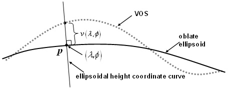
Figure 9.1 — Vertical offset surface for ellipsoidal height
EXAMPLE 2 If an SRF is derived from SRFT LOCAL_TANGENT_SPACE_EUCLIDEAN or SRFT LOCAL_TANGENT_SPACE_CYLINDRICAL, the designated vertical coordinate-component is height and the vertical coordinate-component zero surface is a plane. Given a VOS with respect to the SRF, The vertical offset at a point p in the plane is the distance from p to the VOS along a line normal to the plane (see Figure 9.2).
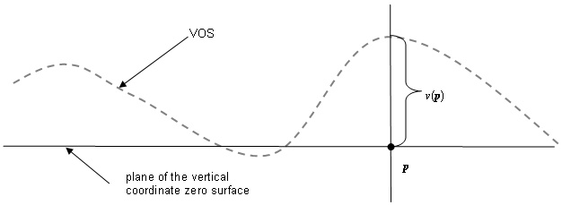
Figure 9.2 — Vertical offset surface tangent plane
9.4 Geoidal separation
If the VOS is a geoid, ![]() is
called the geoidal
separation at
is
called the geoidal
separation at ![]() (see Figure 9.3). The specification of the geoidal separation is equivalent
to the specification of the geoid surface because the geoid DSS can be
constructed from the set of geoidal separation values.
(see Figure 9.3). The specification of the geoidal separation is equivalent
to the specification of the geoid surface because the geoid DSS can be
constructed from the set of geoidal separation values.
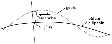
Figure 9.3 — Geoidal separation
NOTE The
geoidal separation is often published as a table of values of![]() .
.
9.5 Vertical offset height and elevation
Given a VOS with respect to an SRF with vertical coordinate-component h, the vertical offset height he at point p is defined as he = h - v(p) (see Figure 9.4).
EXAMPLE If the SRF is derived from SRFT CELESTIODETIC and If (λ, φ, h) is the coordinate of p, then he = h − v(λ, φ).
If the VOS is a geoid, then he is called the elevation of p with respect to the geoid. Note that in the geoid case, (ellipsoidal height) - (elevation) = v(λ, φ).
NOTE 1 he is an approximation of the distance from p to the VOS. In general, the vertical coordinate-component curve intersection with the VOS is not perpendicular to the VOS. When the intersection is not perpendicular, he does not equal the distance.
NOTE 2 VOS is similar in concept to vertical datum as defined in ISO 19111. ISO 19111 uses the term vertical datum to define a vertical coordinate reference system as part of a (3D) compound coordinate reference system.
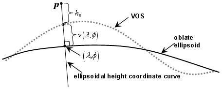
Figure 9.4 — Vertical coordinate-component with respect to a vertical offset surface
9.6 Use of vertical offset height in spatial referencing
If a DSS is a VOS for a 3D SRF, and c = (c1, c2) is a surface coordinate in the induced surface SRF, then c together with vertical offset height he represent a unique location in object-space. If v(c) is known, then the SRF 3D coordinate of that location is (c1, c2, he+ v(c)). In this case, the 3D coordinate may be changed to other SRF coordinate representations in accordance with the operations specified in Clause 10.
In general, the value of v(c) is not known. In that case, the 3D SRF coordinate of the location cannot be computed nor can it be changed to a different SRF. An important exception is the case of two 3D SRFs, SRFS and SRFT, that:
a) use the same ORM, and
b) use the same vertical coordinate-component.
In this case, if cS = (c1S, c2S) is a coordinate in the induced surface SRF of SRFS and if cT = (c1T, c2T) is the coordinate in the induced surface SRF of SRFT for the same surface position, then cS with vertical height he in SRFS and then cT with vertical height he in SRFT represents the same location in object-space.
EXAMPLE SRFS is derived from SRFT LAMBERT_CONFORMAL_CONIC with ORM WGS_1984 and SRFT is derived from SRFT MERCATOR with the same ORM and p is on the ORM ellipsoid RD and is in the valid-region of both SRFs. If cS = (c1S, c2S) and cT = (c1T, c2T) are the surface coordinates of p in the respective SRFs, then cS with vertical height he in SRFS and cT with vertical height he in SRFT represents the same location in object-space.
9.7 Other vertical measurements
In addition to vertical offset height (and elevation), different fields of application define other vertical measurements. These include:
a) Orthometric height ho depends on a gravity model that specifies a potential for each position in position-space. The gradient operator on the geoidal equipotential surface specifies a vector field in position-space. A plumbline is defined to be a curve that follows the gradient vector field (i.e., the tangent vector at a point on the plumbline equals the potential gradient vector at that point). Let q be a position in position-space. The plumbline containing q intersects the geoid at a position p. The orthometric height of q is the plumbline arc length distance from p to q (see Figure 9.5). Note that the tangent to a plumbline at the point where the plumbline intersects the geoid is normal to the geoid.
b)
Other specific functional
relationships of the form hm = f(u, v, h), where f is strictly monotonic
in h for fixed u and v (or in the geodetic case: ![]() for fixed
for fixed ![]() ).
).
EXAMPLE An example of a monotonic function of h used in vertical measurement is the standard pressure altitude function.
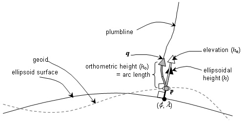
Figure 9.5 — Orthometric height and elevation
NOTE Terrain elevation is not a standardized term and can have several different definitions and, consequently, different values depending on the application domain. The phrase “height above mean sea level” is ambiguous for several reasons. In addition to the varying definitions/approximations/models of the mean sea level VOS, height can be measured along a straight line normal to the surface or along a plumbline (plumbline curves may be empirical or depend on the gravity model used). These height measurements are called gravity-related heights in ISO 19111. The Global Positioning System uses ellipsoidal height referenced to the ORM_WGS84 ellipsoid.
9.8 Geoidal and equipotential DSS specifications
The elements of a DSS specification are defined in Table 9.1. This International Standard specifies in Table 9.2 and Table J.20 a DSS collection of geoids and equipotential surfaces for celestial bodies. Additional geoids or equipotential surfaces may be registered in accordance with Clause 13.
In general, if the gravity equipotential surface of a DSS and the oblate ellipsoid RD of an object-fixed ORM have both been selected to approximate the surface of a planet, then the DSS will be a VOS with respect to any SRF with a specified vertical coordinate-component of ellipsoidal height based on that ORM. In particular, all the geoids specified in Table 9.2 for the Earth are VOSs with respect to the standard SRFs for object Earth that specify a vertical coordinate-component of ellipsoidal height provided the applicable regions intersect. In these cases the API provides an SRF class method for the computation of the geoidal separation if the DSS specification includes a DSS model.
Table 9.1 — Geoidal and equipotential DSS specification elements
|
Element |
Definition |
|
DSS label |
The DSS label (see 13.2.2). |
|
DSS code |
The DSS code (see 13.2.3). |
|
Description |
The published name of the DSS |
|
Global/local |
Specifies whether the DSS is local or global relative to the object. |
|
Model |
A DSS model specification; otherwise “none”. |
|
References |
The references (see 13.2.5). |
|
Notes |
Additional, non-normative information. |
Table 9.2 — Geoidal and equipotential DSS specifications
|
Element |
Specification |
Element |
Specification |
|
DSS label |
DSS code |
1 |
|
|
Description |
WGS 84 EGM 96 geoid |
Global/Local |
Global |
|
Model |
Specified in the reference. |
References |
[83502T, Section 6] |
|
Notes |
The geopotential surface defined by the Earth gravitational model (EGM) WGS 84 EGM 96 that is closely associated with the mean ocean surface. This is an ORS model. |
||
|
DSS label |
DSS code |
2 |
|
|
Description |
International Great Lakes datum (IGLD) 1955 |
Global/Local |
Local |
|
Model |
none specified |
References |
[IGLD79] |
|
Notes |
A system of geopotential elevations throughout the Great Lakes region that is based on mean water level at Pointe-au-Pere, Quebec, on the Gulf of St. Lawrence over the period 1941 through 1956. Implemented January 1, 1962. |
||
|
DSS label |
DSS code |
3 |
|
|
Description |
International Great Lakes datum (IGLD) 1985 |
Global/Local |
Local |
|
Model |
none specified |
References |
[IGLD85] |
|
Notes |
A revision of the International Great Lakes datum 1955 to address the effects of crustal movement, the development of a common datum between Canada, the United States, and Mexico, new surveying methods, and the deterioration of the zero reference point gauge location. It is based on mean water level at Rimouski, Quebec, on the Gulf of St. Lawrence over the period 1970 through 1988. Implemented January 1, 1992. |
||
|
DSS label |
DSS code |
4 |
|
|
Description |
Mean sea level (MSL) |
Global/Local |
Global |
|
Model |
none specified |
References |
[BOWD, Section 913] |
|
Notes |
A continuous surface over the oceans (or its hypothetical extension under the land masses) defined by the mean of sea level surfaces approximated and observed over 19 years. A conceptual surface without a specific DSS model. |
||
|
DSS label |
DSS code |
5 |
|
|
Description |
North American vertical datum (NAVD) 1988 |
Global/Local |
Local |
|
Model |
none specified |
References |
[NAVD88] |
|
Notes |
A fixed reference for elevations derived from a general adjustment of the first-order terrestrial levelling nets of the United States, Canada, and Mexico. In the adjustment, only the height of the primary tidal bench mark, referenced to the International Great Lakes Datum of 1985 local mean sea level height value, at Pointe-au-Pere, Quebec, on the Gulf of St. Lawrence was held fixed, thus providing minimum constraint. |
||
|
DSS label |
DSS code |
7 |
|
|
Description |
Ordnance survey geoid model (OSGM) 2002 |
Global/Local |
Local |
|
Model |
none specified |
References |
[OSGM02] |
|
Notes |
The geopotential surface defined by the OSGM of 2002, covering the region of Great Britain, 45,5ºN to 61,5ºN and 3,5ºW to 11,5ºE (SRF GEODETIC_WGS_1984). |
||
|
DSS label |
WGS84_ELLIPSOID |
DSS code |
8 |
|
Description |
WGS 84 ellipsoid |
Global/Local |
Global |
|
Model |
Specified by |
References |
[83502T, Section 3] |
|
Notes |
The oblate
ellipsoidal figure of the Earth defined by WGS 84. This is a VOS for all SRFs with
ellipsoidal height as the vertical coordinate-component and that are based on
ORM WGS_1984. For those SRFs, |
||
|
DSS label |
DSS code |
9 |
|
|
Description |
WGS 84 EGM 84 geoid |
Global/Local |
Global |
|
Model |
Specified in the reference. |
References |
[83502T, Section 6] |
|
Notes |
The geopotential surface defined by the Earth gravitational model (EGM) WGS 84 EGM 84 that is closely associated with the mean ocean surface. This is a DSS model. |
||
|
Object type: Planet (non-Earth) |
|||
|
Object type: Satellite |
|||
|
Object type: Star |
|||
NOTE There are no entries in Table 9.2 for non-Earth objects. Such entries may be added by registration (see Clause 13).