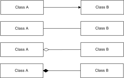
Figure 4.2 — UML associations
Table 4.1 lists the topics of this clause. Each entry in the list contains a hyperlink to the corresponding subclause. Clicking on the “⇒” symbol that precedes some entries will toggle the display of lower level subclause entries.
This clause describes the concepts of this part of ISO/IEC 18023 and how they interact with each other to provide cohesive and consistent data representation. Provision is made for representing data to the level of detail necessary to support a variety of information technology applications that will use or depend on environmental data using the concepts specified in this part of ISO/IEC 18023.
Throughout this standard, special conventions and notations are formatted to distinguish between and add emphasis to various computer-related or SEDRIS-specific terms. Table 4.2 specifies the notation used in this part of ISO/IEC 18023.
Table 4.2 — Document conventions and notation
|
Convention |
Example |
Description |
|---|---|---|
|
<DRM Class> |
Data Representation Model (DRM) class names with the underscores replaced by spaces and the name enclosed in angle brackets (e.g., DRM_Colour_Index = <DRM Colour Index>) |
|
|
Monospace font |
FALSE |
Programming constructs including data type names and declarations, enumerated and selection data type values, field names, function parameter names, equations, and pseudo-code. |
|
Bold sans-serif font |
Consider a <DRM Polygon> instance P. |
Names of specific constructs such as DRM class instances. |
|
Italics |
ISO 639:1988, Code for the representation of names of languages. |
Document titles |
|
not always |
for a word or phrase when introduced in text for definition, explanation, or discussion |
|
|
Names of abstract DRM classes |
||
| 8 Spatial reference surfaces of ISO/IEC 18026 | References to portions of other International Standards. |
DRM class names are used in the text either as nouns or as adjectives. When
used as nouns, DRM class names refer only to the DRM class. When used as
adjectives, DRM class names modify the noun to which they apply. Except when
that noun is “class” or “subclass”, the noun refers to an instance of that
class. If the DRM class is being used as an adjective, the noun refers to an
instance of a concrete subclass of that class.
Accurate and unambiguous representation of environmental data is an important part of many information technology applications. This part of ISO/IEC 18023 permits representations of environmental data that can be described accurately, unambiguously, and precisely.
Authoritative representations of the environment are expected to be internally consistent and conform to physics-based principles. Furthermore, representations of environmental data shall contain an appropriate integration of terrain, ocean, atmosphere, and space domain data about a region of interest. This part of ISO/IEC 18023 supports the representation of the physical as well as the abstract aspects of each environmental domain. In addition, the actual reference objects being modelled or described can be either natural (e.g., some region of the Earth) or some constructed object. This latter capability is important in applications that evaluate the characteristics and performance of constructed objects with respect to environmental effects and impacts, prior to production (e.g., testing and evaluating land, water, air, and space vehicles).
This part of ISO/IEC 18023 also supports the representation of 3D models, including various articulations required to convey general system design characteristics, as well as data representation in the environmental domains of:
A representation of the terrain domain includes data on the location and characteristics of a planetary surface, natural and permanent or semi-permanent constructed features, and related processes including seasonal and diurnal variation.
EXAMPLE 1 soil and subsurface characteristics
EXAMPLE 2 surface elevations
EXAMPLE 3 vegetation
EXAMPLE 4 roads
EXAMPLE 5 signs
EXAMPLE 6 vehicles
EXAMPLE 7 buildings with interiors and included objects
The terrain also includes inland waters, as well as the ocean bottom (e.g., bathymetry and sediment types).
A representation of the ocean domain includes data on the location and characteristics of natural and constructed features and description of the dynamic processes of the liquid planetary surface and subsurface.
EXAMPLE 8 wave heights
EXAMPLE 9 depth pressure
EXAMPLE 10 vessels
EXAMPLE 11 buoys and impediments to navigation
EXAMPLE 12 temperature
EXAMPLE 13 salinity gradients
EXAMPLE 14 acoustic phenomena
A representation of the atmosphere domain includes data on the characteristics of the gaseous envelope surrounding a planetary object and location and characteristics of liquid or solid particles contained within an atmosphere.
EXAMPLE 15 particulate and aerosol data on haze, dust, and smoke
EXAMPLE 16 clouds
EXAMPLE 17 atmospheric pressure
EXAMPLE 18 wind
EXAMPLE 19 precipitation
EXAMPLE 20 humidity
EXAMPLE 21 obscurants
EXAMPLE 22 contaminants
EXAMPLE 23 nuclear/biological/chemical effects
EXAMPLE 24 radiated energy
EXAMPLE 25 temperature
EXAMPLE 26 illumination
For the Earth, the atmosphere domain is specified to include the zone extending from the planetary surface to the lower mesosphere as part of a general transition area to the space domain.
A representation of the space domain includes data on the location and characteristics of regions beyond the specified upper boundary of a planetary atmosphere.
EXAMPLE 27 stars and the interstellar medium
EXAMPLE 28 natural or constructed celestial objects
EXAMPLE 29 neutral and charged atomic and molecular particles and their optical properties
EXAMPLE 30 solar winds
EXAMPLE 31 space weather
EXAMPLE 32 electromagnetic effects
For the Earth, the space domain generally lies beyond the upper stratosphere as part of a general transition area from the atmosphere domain.
The boundaries of the various environmental domains are not precisely defined. An application may combine several environmental domains as appropriate to fulfill requirements. The challenge in such combinations is to ensure that consistency and correlation are achieved in the resulting representations of environmental data. This part of ISO/IEC 18023 provides the common framework for meeting this challenge.
This part of ISO/IEC 18023 enables environmental data to be modelled to meet the requirements of applications. The Data Representation Model (DRM) supports the creation of data models that allow an application to completely and accurately represent environmental data while ensuring that such data can be understood and used by another application.
The DRM supports a wide variety of concepts including:
The same environmental object may be represented using the DRM in different ways for different purposes. These purposes include:
EXAMPLE 1 A building may be represented as:
EXAMPLE 2 A bridge may be represented in multiple ways for different purposes:
By permitting multiple representations, the DRM allows sufficient expressive capability for different applications and purposes without requiring that all applications be able to understand all representations.
The ability to support multiple forms of representations is called representational polymorphism. Representational polymorphism allows a variable, function, or object to have more than one representation. The DRM supports representational polymorphism by specifying classes that allow multiple, independent representations of environmental data to be created and the relationships among these representations to be expressed.
EXAMPLE 1 A road may be represented using:
Neither representation changes the nature of the road. Each reflects a different application’s requirements for representing a road.
EXAMPLE 2 A cloud may be represented using:
Neither representation changes the nature of the cloud. Each reflects a different application’s requirements for representing a cloud.
Relationships among multiple representations may be explicitly expressed in the DRM by specifying associations between pairs of representations, generally indicating that one form is an alternate representation of the other (see 4.5.4.4 Associations).
The data organization capabilities in the DRM (see 4.6.10 Organizing principles) permit multiple, alternative organizations to be represented without requiring that any single, specific organization be present.
This part of ISO/IEC 18023 provides an infrastructure for the representation of environmental data with a subsequent ability to support interchange of that environmental data. Two aspects of the interchange of environmental data are the creation of the data (i.e., production) and the use of the data (i.e., consumption).
A producer may create data for a variety of purposes including tailoring environmental data for use by a particular customer or application. Such purposes are supported through the use of a common object model (the DRM as specified in this part of ISO/IEC 18023), a common file format (the SEDRIS abstract transmittal format specified in part 2 of ISO/IEC 18023), and specific encodings such as that specified in part 3 of ISO/IEC 18023. Access to environmental data is through the API specified in 8 Application program interface (API)).
The unambiguous and efficient representation and interchange of data is a precondition to interoperability. Data interoperability occurs when the producing and consuming applications can both unambiguously understand the organization, the meaning, and the context of the environmental data. While interoperability is not always perfectly achieved in practice, this International Standard specifies the mechanisms that make environmental data interoperability possible.
This part of ISO/IEC 18023 supports the creation and reuse of environmental data by providing a common representational mechanism. The DRM, EDCS, and SRM together make it possible for various applications to represent their environmental data in ways peculiar to their own requirements. When augmented with the SEDRIS API and standard encodings, the DRM, EDCS, and SRM also enable the sharing and reuse of this environmental data by others.
As a common environmental data interchange mechanism, it is not necessary that SEDRIS capture the unique requirements of each and every application. Rather it is sufficient to provide a common means for the data to be represented, accessed, and consumed as needed by the application. Each application's requirements for such data may differ, and are often driven by the context of the application. The processing of the data to satisfy those requirements is therefore part of the consuming application’s responsibility (and to some extent outside the domain of the interchange mechanism). This part of ISO/IEC 18023 makes it possible for such processing to be feasible by allowing data to be viewed from different perspectives and by providing data access facilities so that the interface to data can be tailored to a given view and context under application control.
Different producers specialize in different aspects of environmental data production. This part of ISO/IEC 18023 is designed to allow data models to be created using content from different producers. By enforcing a standard data representation model for creating this data, consumers are able to mix data from different producers according to their differing strengths.
EXAMPLE 1 In a virtual tourism application, the following content might be provided by different producers:
EXAMPLE 2 In a training application, different producers might provide:
There are many applications where sharing of data from many producers would be appropriate. This part of ISO/IEC 18023 facilitates the amalgamation of this data within the infrastructure defined by the application using the DRM.
This part of ISO/IEC 18023 is fundamentally about two key objectives:
To achieve these objectives, this part of ISO/IEC 18023 relies on five core technology components. These are:
Three of the core technology components of SEDRIS (DRM, EDCS, and SRM) are used to achieve the first objective. The combination of these three core technology components provides the mechanism for describing and articulating environmental data. This capability makes SEDRIS analogous to a language designed for describing data about the environment.
The second objective builds upon the first, and provides the ability to interchange and share environmental data. The API and the standardized concrete encodings provide the practical means for the interchange of environmental data that can be described through the combined use of the DRM, the EDCS, and the SRM.
The EDCS and the SRM have been designed as independent technologies that can be utilized by other applications or in other data representation schemas. Therefore, this part of ISO/IEC 18023 depends on EDCS and SRM as companion standards. These are briefly described in 4.4 Related standards and their use.
The DRM provides the technology necessary to express the representation of an environmental object. Representation of an environmental object requires a data model that allows:
The DRM relies on ISO/IEC 18025, however, for describing the semantics of what an object is (classification) and what characteristics it has (attribution). These descriptions use the entries in the EDCS. New environmental concepts can be added to the EDCS dictionaries without changing the DRM.
Similarly, the DRM relies on ISO/IEC 18026 for specifying the spatial location of an environmental object, its spatial extent, and/or its components in a proper spatial reference frame (SRF). SRFs, coordinate systems, datums, and other spatial characteristics for the expression of location information can be added to the SRM without impacting the DRM. This allows the DRM objects to use the necessary SRF to express location information of environmental objects, but leaves the complexities of the derivation and expression of the underlying mathematical concepts to the SRM.
Specific DRM classes are provided for creating DRM objects that hold values for location, classification, and attribution. The DRM classes used for the expression of location data use the SRF concepts from the SRM. The DRM classes that deal with the classification and attribution of environmental objects use the EDCS dictionary entries to express object-level semantics.
The DRM objects used for location, classification, and attribution can be aggregated by other DRM objects used to express environmental objects as data primitives or assign them to organizational containers. To express a given environmental object or concept in a specific and appropriate data model, a set of DRM objects is instanced to represent that object or concept.
Data primitives include constructs for the representation of points, lines, surfaces, volumes, meshes, networks, and n-dimensional point-sampled data. Such primitives, along with their location data, classification, and attribution, can be organized in various hierarchies, including by classification, spatial extent, time, and spatial relationships. Such organizations support the creation of unique sets of environmental data tailored to specific applications.
The DRM, in conjunction with the EDCS and the SRM, can also be used to specify environmental data requirements by data modellers for a specific system or application. In these cases, no particular instance of DRM-based data is created, but rather the DRM is used to express a specific data model.
Whether the DRM is used to express a particular data model or instance of specific data, DRM objects may have relationships with other DRM objects in three different manners:
When such a relationship exists, the DRM object will be related to other DRM objects that are its aggregates, components, or associates, respectively. The nature of the allowed relationships is generally described in 4.5 DRM syntax and is specifically described for each DRM class in 6.2 DRM class specifications.
A hierarchy of DRM class instances organized according to the principles described in this part of ISO/IEC 18023 is called a transmittal. A transmittal contains only DRM objects with the representation and relationships prescribed by the DRM. A transmittal provides a standard medium for the interchange of environmental data.
Within this context, there are SEDRIS users who produce environmental data and there are SEDRIS users who consume the environmental data. Consumers of SEDRIS data use transmittals as inputs into specific applications or processes. SEDRIS data producers generate transmittals as output of their applications or processes. There need not be a one-to-one relationship between data producers and consumers; i.e., a data producer may generate data for more than one consumer and a consumer may receive data from more than one data producer.
transmittals themselves are not an interchange mechanism. Instead, they provide the media-based form for the exchange of environmental data. As a result, there is a requirement for storing the information contained within a transmittal in a form that allows its transport between SEDRIS implementations. This requirement is satisfied through the ATF, as specified in part 2 of ISO/IEC 18023. Other parts of ISO/IEC 18023 specify the encodings for the ATF that describe the actual form in which data is stored. While the forms provided by each encoding may differ, the information content is the same for the same transmittal. In particular, part 3 of ISO/IEC 18023 specifies a binary encoding referred to as the STF. 4.3.3.2 Accessing transmittals using the API describes the mechanism that allows applications to be decoupled from specific transmittal encodings. Therefore, applications do not need to be concerned about the transmittal encoding used, and instead can interact with any encoding in exactly the same manner, via the API.
ITR is the mechanism that allows relationships between objects contained in different transmittals.
EXAMPLE An aggregate in one transmittal can have an ITR reference to a component object in a different transmittal.
Relationships that use ITR follow the DRM relationship rules. Those DRM objects that can create relationships through ITR are limited by the DRM constraint, 7.2.59 Publishable object. DRM objects that satisfy this constraint are termed publishable.
The API allows access to, and manipulation of, transmittals. The API decouples the user’s application from the specific format of the transmittal. It also provides access functions that allow data extraction independent of the transmittal’s data organization or presentation. It does this by allowing the calling applications to set a specific extraction context through filters. Under these conditions only data that matches the filter criteria is returned to the calling application. The key API concepts and overall characteristics of the API are specified in 4.19 Application program interface (API), and the specific functions are described in 8 Application program interface (API).
This part of ISO/IEC 18023 depends on other International Standards for specifications that are also applicable outside of the SEDRIS milieu. The following describe the primary companion standards required by this part of ISO/IEC 18023.
The concepts embodied by the DRM require specifying semantic information about the environmental data being represented. This information is provided in the form of classifications of the environmental objects and attributes specifying properties of such objects. ISO/IEC 18025 specifies the allowed classifications and attributes and also provides a mechanism for specifying new classifications and attributes. Since attributes have data associated with them, ISO/IEC 18025 also specifies codes for indicating the units of measure in which numeric attribute values are specified and codes for selecting enumerated values. A standard API is provided for specifying EDCS codes and attributes as well as a functional API for converting values from one unit to another.
The spatial concepts used relating to coordinate systems within part of ISO/IEC 18023 are specified in ISO/IEC 18026. The SRM specifies the mechanisms and the structure of SRFs as well as the formal definitions for specific SRFs (8 Spatial reference frames), the coordinate systems used within them (5 Abstract coordinate systems), and the reference objects to which they are attached (7 Reference datums, embeddings, and object reference models). 10 SRF operations of ISO/IEC 18026 specifies standard functionality for converting spatial positions and/or directions from one SRF to another. Representation of spatial data as well as the means of converting between representations is provided by the SRM API specified in 11 Application program interface of ISO/IEC 18026.
Metadata concepts used in this part of ISO/IEC 18023 are built on the concepts specified in ISO 19115 — Geographic information — Metadata.
Through the use of the DRM, users of this part of ISO/IEC 18023 can describe and articulate their environmental data clearly while simultaneously using the same representation model to understand data from other users unambiguously. The DRM is an object-oriented data representation model and provides a unified method for describing all data elements and their logical relationships needed to express environmental data in a seamless manner across all environmental domains.
A data representation model defines the manner in which specific data models can be represented, independent of any specific data content. A data representation model can be thought of as a meta-“data model”. The DRM defines object classes and relationships that allow a wide variety of environmental entities and/or phenomena to be represented as abstract forms, tables and grids, images, and/or forms that more closely resemble the geometric shape and configuration of the entity.
Generally, a data model defines individual classes to represent specific types of real-world entities or phenomena. A data model is the specific set of data structures, and their relationships, that specify the unique instance of data about a concept or an object. A data model is usually directly tied to the entity or concept it models. Attributes specific to each entity's class are “built-in” to the class definitions. The semantics of what specific entity or phenomenon a given class represents is captured by the name and the attributes of that class. Often, data models are realized as a specific and rigid format or schema.
In contrast, a data representation model defines a mechanism where a variety of data can be modelled and represented through a common set of classes. The semantics and attributes of the specific entity or phenomena that a particular class represents are factored out. These are modelled as separate components of a given common class.
The DRM contains classes that can represent physical locations, and “property” classes that describe various characteristics through the use of EDCS. Such fundamental constructs in the DRM, along with its primitive classes for the representation of environmental data, can be used to model and instance any set of environmental objects. Since the primitive classes used in the representation are independent of any specific environmental object, and since such classes can contain other classes that use the EDCS to specify the semantics and the attributes of an object, different environmental entities or phenomena can be represented with the same classes.
Separating the semantics of what something is from the “data primitives” that can represent the thing is a fundamental concept in this part of ISO/IEC 18023. An equally important concept is the factoring out of the common syntax and structural semantics of data models that are used to describe “similar things”. Combining these two methods (along with other important concepts that will be discussed later) allows a single schema to represent a large variety of possible data models.
This part of ISO/IEC 18023 uses Unified Modelling Language (UML) as specified in ISO/IEC 19501 to model the DRM classes. UML notation is used to describe class diagrams as well as object diagrams that describe example instances of the data conforming to the related class diagrams. This subclause describes the extensions and deviations to conventional UML usage.
UML describes object classes by providing the name, a set of attributes, and a set of operations or behaviours that can be performed by objects of that class. It provides this information by a rectangular box having three segments as shown in Figure 4.1
Abstract classes (i.e., those that cannot be instantiated) are distinguished from concrete classes (i.e., those that can be instantiated) by depicting the name of the abstract class in italics.
The DRM class diagrams, provided in 6.2 DRM class specifications, omit the operations. The UML attribute listings are also provided in 6.2 DRM class specifications, but are referred to as field elements. Hence, there is a mapping between UML attribute elements and DRM field elements. In instance diagrams, the field elements are provided in the second rectangular box, consistent with UML. DRM classes contain all field elements defined within their class definition as well as all inherited from their abstract classes. As a result, all instances of the same class have the same set of field elements and the field elements of a class are specified to reside within the concrete classes regardless of whether the field element was inherited or not.
UML defines an association as a semantic relationship between two or more classes. In UML each end of the association has an IsNavigable Boolean attribute that determines if a class has access to the another class as specified in 2.5.2.3 of ISO/IEC 19501. UML navigability is specified within this part of ISO/IEC 18023 by defining either one-way or two-way directionality. One-way association means that only one class is aware of the association relationship (as indicated by one end of the association having the UML attribute IsNavigable set to FALSE). If there is a one-way association of A and B, and A is aware of the association, it is said that A is associated to B and B is associated by A. In two-way associations, both classes are aware of the relationship (as specified by both ends of the association having the UML IsNavigable attribute set to TRUE. Hence, if A and B have a two-way association, A is associated to B and A is associated by B, as well as B is associated to A and B is associated by A. All of the relationships of a two-way association are conveyed by the statement “A is associated with B".
UML specifies a set of association relationships termed aggregation and composition. Aggregation is specified as a whole to part relationship in which instances cannot have cyclic aggregation relationships. Composition is specified as a form of aggregation with strong ownership where the lifetime of the “owned” is dependent on the “owner”. The examples in Figure 4.2 provide the UML graphical representation for a one-way association, two-way association, aggregation and composition between classes A and B respectively. In one-way associations, an arrowhead is used to show object B is associated by object A. The solid line without arrow heads indicates a two-way association between two objects. For simplicity, the arrowheads at each end of a two-way association are not included in the diagrams; instead, simply a plain, solid line is used. Aggregation is represented with an open diamond attached to the aggregating class. Composition is represented with a solid diamond attached to the whole. The composition relationship is not required and is not used in this part of ISO/IEC 18023.
In this part of ISO/IEC 18023, UML aggregation is used to denote the whole-to-part relationship between object classes. Within object pairs that have an aggregation relationship, aggregating objects are termed aggregates, whereas aggregated objects are termed components as defined in 4.3.2.2 Expression of environmental data and data models with the DRM.
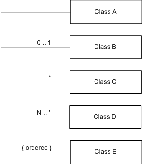
Multiplicity, the number of components allowable in the aggregation, and optional relationships are denoted in UML by providing a lower limit and an upper limit in the form: <lower limit> .. <upper limit>. A one-to-one relationship between two classes would be expressed as “1 .. 1”, at each end of the relationship. In this part of ISO/IEC 18023, the same rule is applied with some minor modifications. The multiplicity of a relationship between a class A and a class B indicates, for a given instance of A, the number of instances of B that may participate in such a relationship with A. For component relationships, if B is a formal component of A, the multiplicity for A in the relationship indicates how many instances of A can share B. Relationships between classes specify the legal possibilities, while relationships between objects shall comply with those possibilities.
If the multiplicity is exactly one as in Class A in Figure 4.3, the numbering can be removed. Class B is an optional relationship that follows the UML notation. Class C also follows UML notation by using the “*” character to denote “zero or more”. Class D states a minimum per the UML notation. Finally, Class E indicates that a specific ordering exists between object classes.
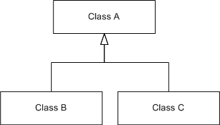
The UML generalization relationship, as denoted in Figure 4.4, is used in this part of ISO/IEC 18023. Here, classes B and C are both a subclass of class A, and both inherit from class A.
A link is a relationship between two class instances and shall be unique between the class instances. Multiple links are allowed between two class instances provided they are differentiated through one of the optional UML mechanisms of role names, relationship names, or association classes. In this part of ISO/IEC 18023, no DRM class instance will have multiple links to another class instance without using an association class. An association class is a class that specifies the semantics of a relationship between classes. Such a class is termed a link class. Instances of link classes are termed link objects. Link objects specify information that applies to the specific relationship between the two class instances. In the DRM, some association and component relationships have a link class associated with the relationship. The notation for link class is shown in the Figure 4.5 where the box containing “Class C” represents the link class:
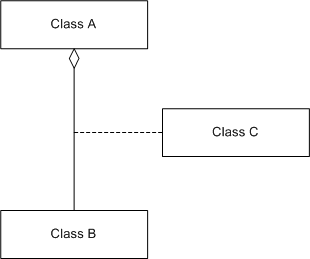
Figure 4.5 — Link class notation
There are hundreds of classes in the DRM. These classes can be grouped into a small number of categories based on whether they describe:
The geometry classes include such primitives as points, vertices, lines, arcs, polygons, and volumes. They also include point sample data represented in n-dimensional uniform and non-uniform grids, including finite element meshes.
The feature classes include such primitives as point features, linear features, and areal features.
Both feature and geometry primitives have their own independent topology data classes for describing mathematical and physical connectivity.
Attributes include such items as location, colour, sound, classification, metadata, and extents.
Data organization classes include methods for organizing data by such concepts as time, distance, classification, spatial relationships, and state. Libraries can also be considered as data organization schemes. Libraries allow for storage savings by reuse of shareable items through referencing an instance of an item in a library.
Explicit relationships describe association between various classes.
To separate the evolution of the DRM from the evolution of the API, each class in the DRM is not treated as an independent class with its own methods. Instead, all classes in the DRM inherit from a single “superclass”.
All classes in the DRM are either concrete or abstract; that is, either they can or cannot be instantiated as actual objects in a transmittal. Abstract classes cannot be instantiated, and therefore never correspond directly to physical objects or environmental data. Instead, they are used to abstract information that is common to their subclasses, such as relationships with other classes in the DRM or data fields. Abstract classes always have subclasses, which may themselves be abstract or concrete.
Concrete classes, on the other hand, can be instantiated directly. In this part of ISO/IEC 18023, concrete classes never have subclasses. Therefore, in this part of ISO/IEC 18023, superclasses are always abstract.
An example of abstract versus concrete classes is shown in Figure 4.6:
In Figure 4.6, A is an abstract class with two subclasses, B and C, where B is also an abstract class, but C is a concrete class. Instances of class C may appear in a transmittal, but A and B cannot be instantiated. Since C is a subclass of A, any instance of C is conceptually a member of A as well. Any instance of a concrete class descended from B is also conceptually a member not only of B, but also of A.
In discussing abstract classes and their characteristics, references will be made to instances of the concrete classes that are subclasses (or subclasses of subclasses) of the abstract class. When speaking of these instances, for brevity they may be referred to as “instances” of the abstract class.
An aggregation relationship between two classes A and B may be called a “has-a” relationship, because an instance of A is considered to “have” instances of B as components. In terms of relationships between classes, B is called a formal component of A, and A is called a formal aggregate of B. An instance of A is said to have instances of B as components, while an instance of B has one or more instances of A as aggregates. The multiplicity of the formal relationship specifies for an instance of A exactly how many instances of B it can have as components, and for an instance of B how many instances of A may aggregate it.
Both abstract and concrete classes may participate in relationships as either formal aggregates or formal components. If an abstract class A is a formal aggregate of some class C, all subclasses of A are also formal aggregates of C; the relationship is said to be inherited from A. Likewise, if an abstract class X is a formal component of some class Y, all subclasses of X may be substituted for X in the relationship when concrete subclasses are instanced as actual objects.
EXAMPLE Consider a case where an abstract class “member”, is specified to be a component of at least one “club”, and a concrete class, “senior member”, is a subclass of the class “member”. In this case, an instance of “senior member” is required to be a component of at least one instance of “club”.
In the DRM, the association relation is used in the following cases:
When the relationship from a component DRM class to an aggregation DRM class has multiplicity greater than one, instances of the component DRM class may be shared by more than one instance of the aggregation DRM class.
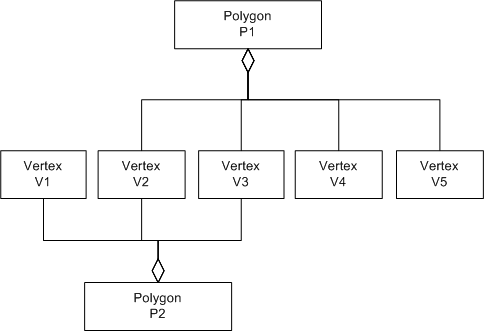
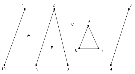
EXAMPLE Consider a class called “polygon” representing a planar surface. A “polygon” instance shall have three or more “vertex” components, each of which may be shared by any number of “polygon” instances. An example using these classes is illustrated below in the instance diagram depicted in Figure 4.7. Within this diagram there are two objects of class “polygon” labeled Polygon P1 and Polygon P2. There are also five objects of “vertex” labeled Vertex V1, Vertex V2, Vertex V3, Vertex V4, and Vertex V5. The multiplicity from the “polygon” class to the “vertex” class is three or more, while the multiplicity from the “vertex” class to the “polygon” class is one or more. Thus, in Figure 4.7, the objects Vertex V2 and Vertex V3 are shared by objects Polygon P1 and Polygon P2.
The syntactic specification of DRM classes, and relationships between classes, does not itself guarantee complete semantic validity.
EXAMPLE A quad-tree that divides a spatial region into four sub-regions may be syntactically specified by defining four quadrants. However, the specification will not be semantically correct unless the four quadrants are disjoint and their union is the original spatial region.
Many DRM classes require additional semantic information to ensure that the use of those DRM classes will be valid. This part of ISO/IEC 18023 specifies a set of constraints that define valid semantic use. These constraints are specified in 7.2 Constraints.
The concepts of this part of ISO/IEC 18023, embodied in the DRM, are depicted using UML as specified in 4.5.3 Modelling technique and notation. UML diagrams are used in the DRM classes specified in 6.2 DRM class specifications. All of the DRM, using several UML diagram pages, is specified in Annex A UML diagrams.
Each DRM class contains the information shown in Table 4.3:
Table 4.3 — DRM class specification elements
|
Property |
Description |
|---|---|
|
Class |
The name of the class being specified. |
|
Superclass |
The name of the superclass for the class being specified. |
|
Subclass |
The names of any subclasses derived from the class being specified. |
|
Definition |
A description of the class. |
|
Class diagram |
A hyperlink to a UML diagram depicting the relationships of the class being specified including its superclass, its subclasses, its associated classes, and the classes of which it is composed. |
|
Inherited field elements |
A specification for each of the fields in the class that are inherited from its superclass hierarchy. This specification is provided for convenience only. The actual specification is contained in the specification of the superclass. |
|
Field elements |
A specification for each of the non-inherited fields in the class, if any. |
|
Default field values |
A hyperlink to the portion of Annex D containing the default field values for the class. |
|
Associated to (one-way) (inherited) |
A list of inherited DRM classes to which the DRM class specified in this table may contain one-way associations. The DRM classes in the list will not have an association to the DRM class specified in this table, but will be associated by the DRM class specified in this table. This is provided for convenience only. The actual list is specified in the superclass. |
|
Associated to (one-way) |
A list of DRM classes to which the DRM class specified in this table may contain one-way associations. The DRM classes in the list will not have an association to the DRM class specified in this table, but will be associated by the DRM class specified in this table. |
|
Associated by (one-way) (inherited) |
The DRM class specified in this table may have one-way associations by the inherited list of DRM classes. The DRM class specified in this table will not have an association to the DRM classes in this list. This is provided for convenience only. The actual list is specified in the superclass. |
|
Associated by (one-way) |
The DRM class specified in this table may have one-way associations by the list of DRM classes. The DRM class specified in this table will not have an association to the DRM classes in this list. |
|
Associated with (two-way) (inherited) |
A list of inherited DRM classes that may contain two-way associations with the DRM class specified in this table. The DRM class specified in this table will have an association with the DRM classes in this list. This is provided for convenience only. The actual list is specified in the superclass. |
|
Associated with (two-way) |
A list of DRM classes that may contain two-way associations with the DRM class specified in this table. The DRM class specified in this table will have an association with the DRM classes in this list. |
|
Composed of (inherited) |
A list of inherited DRM non-metadata classes of which the class being specified is composed in a two-way manner. This specification is provided for convenience only. The actual list is contained in the specification of the superclass. |
|
Composed of (two-way) |
A list of DRM non-metadata classes of which the class being specified is composed in a two-way manner. |
|
Composed of (two-way) (metadata) (inherited) |
A list of inherited DRM metadata classes of which the class being specified is composed in a two-way manner. This specification is provided for convenience only. The actual specification is contained in the specification of the superclass. |
|
Composed of (two-way) (metadata) |
A list of DRM metadata classes of which the class being specified is composed in a two-way manner. |
|
Component of (two-way) (inherited) |
A list of DRM classes that may aggregate the DRM class specified in this table. This specification is provided for convenience only. The actual specification is contained in the specification of the superclass. |
|
Component of (two-way) |
A list of DRM classes that may aggregate the DRM class specified in this table. |
|
Constraints |
A list of constraints that apply to the class being specified. |
|
Clarifications |
More detailed information about the various items in the class specification. |
|
Example(s) |
An example of the use of the class. |
Any DRM object not being used solely as a link object that has an entry in either the “Component of (two-way) (inherited)” or “Component of (two-way)” rows will have at least one aggregate from the entries in these rows.
The full set of DRM class specifications is in 6.2 DRM class specifications.
Several key concepts in the DRM transcend the specification of a particular DRM object. These concepts are treated here. In some cases, these key concepts have an interrelation that a study of individual DRM classes will not reveal. In other cases, the concepts described herein enable a better understanding of the role of individual classes or groups of classes. Where appropriate, each key concept discussed here in general terms is treated in detail later through the description or example of specific classes that embody the concept. A concept that encompasses the complete DRM is the <DRM SEDRIS Abstract Base> class. The <DRM SEDRIS Abstract Base> class is the ancestor of all DRM classes. Concrete DRM class instances will eventually derive from it.
A fundamental characteristic of any environmental object is its location. Whether an object is in the real world or in a fictitious environment, a precise, accurate, and consistent representation of its spatial location, especially in relation to other objects in the environment, is critical to its accurate portrayal. Any number of SRFs can be used to specify the location of an object. In practice, many SRFs exist, and each is designed to serve a particular domain of use or application. Environmental objects within some physical proximity can be represented in different SRFs, if desired or required. Full understanding of the parameters for the specification of each SRF and the interrelationship between SRFs is needed if meaningful representation and use of such environmental objects is expected.
The DRM relies on the SRM concepts specified in ISO/IEC 18026 to represent location data. Similarly, the API in this part of ISO/IEC 18023 relies on the API defined in 11 Application program interface of ISO/IEC 18026 to perform conversions and transformation operations on coordinate values.
Through specific classes designated for the representation of location data, the DRM provides the ability to express 2D, surface, and 3D coordinate values in any number of valid SRFs specified in the SRM. The DRM also permits the coexistence of different SRFs in a transmittal, as long as rules for environmental object relationships are followed.
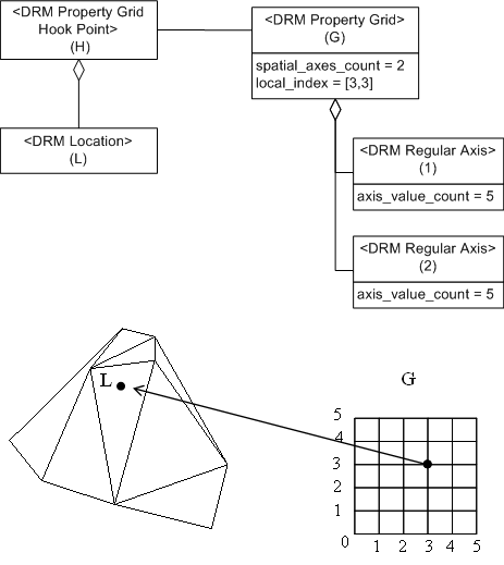
SRFs can be applied to DRM classes that represent a region of the environment (<DRM Environment Root>), a standalone model of an object (<DRM Model>), which can be a complete world unto itself, and a point-sampled grid of surfaces or volumes (<DRM Property Grid>), among others. The DRM supports the expression of coordinates in 2D, surface, and 3D SRFs through a specific set of DRM classes each associated with a particular type of SRF.
SRFs may be specified using three mechanisms:
A particular SRF and its context can be specified by populating an instance of SRF_Context_Info. SRF_Context_Info specifies the parameter values for the desired SRF, a designated spatial surface, and the units of measure for use within the transmittal. More details about the SRF_Context_Info data type may be found in 4.7.2.1 SRFs. See 8 Spatial reference frames of ISO/IEC 18026 for details about specifying SRFs.
In addition, the DRM supports the expression of orientation, scale, and translation of environmental objects, as well as permitting the nested instancing of environmental objects within each other.
These concepts along with the specific DRM classes that embody them are further discussed in 4.7 Spatial concepts.
The DRM separates what an environmental object, or concept, is from how it can be represented. DRM class instances are used to represent environmental objects. However, an environmental object is not fully classifiable from the DRM classes used to represent it. Instead, the DRM uses EDCS classification codes (ECCs) to identify the environmental object. Similarly, EDCS attribute codes (EACs) are used to provide specific characteristics of the environmental object. This separation of representation and semantic classification allows DRM classes to be independent of any specific environmental objects or concepts. This part of ISO/IEC 18023 specifies specific DRM classes used to provide the EDCS codes for environmental object semantics as discussed in 4.8 Semantic attribution in the DRM.
The <DRM Data Table> class represents an n-dimensional array of cells. <DRM Property Grid> is a special version of <DRM Data Table> where at least one of the axes of the table is based on a spatial location. Each cell holds one or more data values whose semantics are specified with EACs. These values are said to be the elements of the <DRM Data Table>. The <DRM Data Table> instance may have as many elements as needed. Each element for a <DRM Data Table> instance has an EDCS_Unit_Code, an EDCS_Unit_Scale_Code, and a data type along with the EDCS_Attribute_Code. This information for all elements is called the signature of the <DRM Data Table> instance. It is also possible for the <DRM Data Table> instance to contain sparse information by representing EDCS value characteristic concepts in the element data.
EDCS classification entries are used to specify the meaning of the entire table. Each axis of a table can be specified independently for its spacing and units. Unlike most other DRM objects, specific API access and manipulation functions exist for handling data tables.
The DRM objects involved in the representation of tabular data are further detailed in 4.9 Data tables.
Certain environmental objects should be represented in a manner as close to their physical appearance as possible. These include the representation of 2D and 3D lines, 2D and 3D solid or point-sampled surfaces, and solid or point-sampled volumes. Often these representations are used in realistic visualization applications. In general, when modelling of an environmental object requires an abstraction that closely resembles its physical appearance and is intended to preserve its geometrical shape, the DRM classes under a branch called geometry representation are used.
Primitive geometry objects include point, line, surface, and volume geometry. In addition, finite element mesh and property grid representations are also considered geometry objects.
The primitive geometry objects can be organized in a number of ways as described conceptually in 4.6.10 Organizing principles and in more detail in 4.13 Organizing principles. Collections of primitive objects when organized in this manner are called geometry hierarchy objects. Each <DRM Geometry Hierarchy> instance can be associated with one or more other <DRM Geometry Hierarchy> instances, as well as with one or more <DRM Feature Representation> instances. This allows a <DRM Feature Representation> or <DRM Geometry Hierarchy> instance to be represented as an alternate representation of a given <DRM Geometry Hierarchy> instance. A complete treatment of geometry representation concepts is provided in 4.10 Geometry representation.
In cases where an environmental object is best represented as a higher abstraction of its physical form or when the environmental object has no realizable physical form, the environmental object is represented conceptually. Such environmental concepts include, but are not limited to, borders between countries, point locations representing an object as a single point, road centre-lines, and outlines of buildings, lakes, or regions. These environmental objects are modelled using feature representations. Often these representations are used in analysis or 2D map applications. In general, when modelling of an environmental object requires a higher degree of abstraction of that object, the DRM classes under the feature representation branch are used.
Primitive feature objects include point features, linear features, and areal features. Unlike geometry objects, the representation of location of feature objects is directly through their topology primitives.
The primitive feature objects can be organized in a number of ways described conceptually in 4.6.10 Organizing principles and in more detail in 4.13 Organizing principles. Each <DRM Feature Representation> instance can be associated with one or more other <DRM Geometry Hierarchy> instances, as well as with one or more <DRM Feature Representation> instances. This allows a <DRM Feature Representation> instance to be represented as an alternate representation of a <DRM Geometry Hierarchy> instance or another <DRM Feature Representation> instance. A complete treatment of feature representation concepts is provided in 4.11 Feature representation.
The DRM provides the <DRM Feature Representation> versus <DRM Geometry Representation> distinction as a mechanism to provide a fundamental separation for representing environmental objects. The distinction between the <DRM Feature Representation> representation and <DRM Geometry Representation> representation is that a <DRM Feature Representation> representation removes all spatial information not required to support spatial connectivity; that is, it only requires topology. The location data of a feature representation is stored within the topology DRM classes. A <DRM Geometry Representation> instance stores location data within the actual representation of the environmental objects. The <DRM Geometry Representation> instnace can then be augmented with topological relationships. Conversely, a <DRM Feature Representation> instance is inherently a topological description. Furthermore, by making this distinction in the DRM, a specific branching point between the two types of representation is provided in the form of a feature representation branch and a geometry representation branch at the second level of a transmittal structure (i.e., at the <DRM Environment Root>).
A second distinction for feature representation versus geometry representation is data application or data usage. A <DRM Feature Representation> representation is more suited to artificial reasoning applications such as route planning and minimizing route costs as in geographic travel systems. While both types of representation can be used by the same application, they are designed for different purposes. Thus, the <DRM Geometry Representation> class is better suited for immersive visualizations, while the <DRM Feature Representation> class is better suited for visualization of abstractions of an environment such as maps.
The association links between <DRM Feature Representation> and <DRM Geometry Hierarchy>, <DRM Feature Representation> and <DRM Property Grid>, as well as the self association of a <DRM Feature Representation> instance to itself and a <DRM Geometry Hierarchy> instance to itself provide a powerful mechanism for the alternate representation of the same environmental object. This polymorphic aspect of the DRM enables it to serve a variety of applications that tend to deal with the same environmental objects but differ in their context or view of that object.
Topology defines the interrelationships between environmental objects. The DRM supports five topology levels for both features and geometry as described in 4.12 Topology. In addition, the DRM provides mechanisms for capturing stacking information (over and under) without the need for three-dimensional topology. Such information is needed by applications that require knowledge of above and below relationships but whose use of topology information is more limited. Examples of such cases include multi-level road network systems and multi-level buildings.
Topology is inherent in the representation of environmental objects as features. The spatial location of feature-based data within the DRM can only be obtained through the use of the topology relationship. Topology of the feature-based environmental objects is often used by applications that require information about connectivity to determine navigation through an environment or adjacency of environmental objects.
Geometry objects may contain full topology about the connectivity of the defining surfaces and facets. However, such topology is not a required part of geometry object representation.
DRM classes used to support geometry and feature topology representations are described in 4.12 Topology.
The DRM allows primitive data to be organized in several different ways including by:
The DRM classes that provide organization hierarchies are found in both the geometry representation and feature representation branches. Each DRM aggregate object acts as a container and can itself contain other aggregate objects.
The geometry representation and feature representation branches each have their own independent aggregate objects, with ten aggregate objects for the feature representation branch and fourteen for the geometry representation branch. Since <DRM Aggregate Feature> is a subclass of <DRM Feature Hierarchy> (which itself is a subclass of <DRM Feature Representation>), and since <DRM Aggregate Geometry> is a subclass of <DRM Geometry Hierarchy>, all association relationships that apply to polymorphic representation of <DRM Feature Representation> and <DRM Geometry Hierarchy> instances also apply to all types of aggregate DRM objects. Aggregate DRM objects not only organize data as needed, they can also associate to other aggregate (and primitive) environmental data at any level of the instanced hierarchy.
A complete treatment of DRM classes used to represent organizing principles is provided in 4.13 Organizing principles.
Libraries fill a special role by allowing a single copy of an item to be referenced or reused one or more times from within the <DRM Environment Root> instance. The following kinds of libraries are supported by the DRM:
Libraries, as a construct for sharing data, are provided in 4.14.3 Libraries.
Models in a <DRM Model Library> instance can be placed in the environment and can be given local attributes that make them appear as if they are unique. This capability in the DRM allows data modellers and data producers to reuse the same <DRM Model> instance numerous times by providing a reference (captured in <DRM Feature Model Instance> and <DRM Geometry Model Instance> classes) from the environment they are modelling to the specific <DRM Model> instance in the <DRM Model Library> instance.
A <DRM Model> instance can be composed of two branches: feature model and geometry model. This allows a <DRM Model> instance to behave analogously to the <DRM Environment Root> instance, where a feature representation and geometry representation branch is provided. A <DRM Model> instance can instance other <DRM Model> instances. This capability can be used to build very complex worlds and reuse them in a broader context.
EXAMPLE A representation of a solar system may include a region of space within the <DRM Environment Root>, where each celestial object can be instanced by pointing to a <DRM Model> in the <DRM Model Library>. Each such model (celestial body) can in turn reference other <DRM Model> instances in order to provide a richer and more complex planetary object.
Alternatively, a single <DRM Model> instance without references to other models can represent a single environmental object (for example, a park bench, a door knob, or a tree) and can be reused within the environment. Each local use within the environment can provide variations to the base model by assigning an orientation or scale, as well as overriding attributes of the base model. Sharing, instancing, and applying transformation to a model are discussed in 4.14.2 Models.
The DRM supports metadata that is intended for use by humans as well as metadata that is used for automated processing and parsing of transmittals. The metadata associated with such concepts as citation, data quality, and points of contact is based on the precepts specified in ISO 19115.
Metadata can be associated with most DRM objects, including organization objects such as aggregates, primitive data, data tables, and libraries.
The metadata associated with the contents of a transmittal is also supported in the DRM to allow automated machine-parsing of transmittals, if such metadata is present. Such metadata includes the following: a transmittal summary, included structures, use of EDCS, DRM classes used, and a summary of primitives and hierarchies used.
A detailed description of all DRM metadata classes is provided in 4.17 Metadata.
In addition to the DRM concepts described here, there exist a number of other important DRM concepts. These concepts are generally a detailed specialization of topics discussed here indirectly, such as transmittal structure, discussed in 4.18 Transmittal structure, and constructs for sharing data discussed in 4.14 Constructs for sharing data. Others are unique to specific application domains, such as animation, control links, visualization parameters for lighting, as discussed in 4.15 Constructs for presenting data and 4.16 Constructs for controlling dynamic data.
Primitives used for expressing location data and the DRM classes that require location data are described below. To provide a basis for understanding spatial concepts of the DRM, the concepts of the SRM are related to concepts of the DRM.
ISO/IEC 18026 defines the concepts required to specify spatial information using the DRM. In the SRM, a spatial coordinate system is is a set of rules by which an n-tuple of real numbers, termed a coordinate, uniquely designates the position of a point in space. An SRF (see 8 Spatial reference frames of ISO/IEC 18026) is a means of combining an abstract coordinate system (see 5 Abstract coordinate systems of ISO/IEC 18026) with an ORM (see 7 Reference datums, embeddings, and object reference models of ISO/IEC 18026) to specify a spatial coordinate system.
An SRF template is an abstraction of a set of specifications of SRFs that share the same abstract coordinate system, coordinate system parameter binding rules, and coordinate-component names and/or symbols. An SRF set is a finite parameterized set of two or more SRFs. Furthermore, 8 Spatial reference frames of ISO/IEC 18026 defines SRF instances by specifying the SRF template parameters for an instance. The DRM provides the ability to store SRF information through all three mechanisms, SRF template parameters, SRF set parameters, and SRF instances.
SRF information is specified in a DRM class via an srf_context_info field. The following DRM classes specify an srf_context_info field:
Each such class specifies its SRF by means of an srf_context_info field, specified using the structured data type SRF_Context_Info. Within this field, the SRF information can be provided as either SRF template parameters, SRF set information, or as an SRF instance code. For 3D SRFs, the srf_context_info field may also specify a DSS that represents a designated spatial surface (see 9 Designated spatial surfaces and vertical offsets of ISO/IEC 18026) to be used in conjunction with some SRFs to provide a reference for the vertical coordinate-component. The specification of each of these data elements is defined in 11 Application program interface of ISO/IEC 18026. In addition, the srf_context_info specifies the units of measure and scales for the coordinate-components.
Coordinates are specified in the DRM as instances of <DRM Location> (see 4.7.3 Location) or as coordinates within gridded data in the scope of a <DRM Property Grid> instance. In the DRM, a coordinate appears only within an DRM object subtree (that is, a tree of aggregate/component relationships) rooted at an instance of a DRM class that specifies the SRF information. The coordinate shall be specified within the SRF specified by the currently applicable srf_context_info field. The context SRF is specified by the nearest aggregating DRM class instance of a DRM class having an srf_context_info field. The coordinate shall belong to a DRM class that is compatible with the SRF specified by the srf_context_info field value. A coordinate is compatible with an SRF if the DRM class corresponds to the SRF template of the srf_context_info field. If the srf_context_info specifies the SRF through SRF template parameters, the SRF template of the srf_context_info field value is specified by the template_code field. If the srf_context_info field value specifies an SRF set, the SRF template of the srf_context_info field value is the SRF template corresponding to the SRF set per 8 Spatial reference frames of ISO/IEC 18026. If the srf_context_info field value specifies an SRF instance, the SRF template of the srf_context_info field value is the SRF template corresponding to the SRF instance per 8 Spatial reference frames of ISO/IEC 18026.
Table 4.4 specifies the DRM class and its corresponding SRF template:
Table 4.4 — DRM class / SRF template correspondence
|
Type |
SRFT label |
DRM class |
|---|---|---|
|
3D |
CELESTIOCENTRIC |
|
|
CELESTIODETIC |
||
|
CELESTIOMAGNETIC |
||
|
EQUATORIAL_INERTIAL |
||
|
HELIOSPHERIC_ARIES_ECLIPTIC |
||
|
HELIOSPHERIC_EARTH_ECLIPTIC |
||
|
HELIOSPHERIC_EARTH_EQUATORIAL |
||
|
LOCAL_SPACE_RECTANGULAR_3D |
||
|
LOCAL_TANGENT_SPACE_AZIMUTHAL_SPHERICAL |
||
|
LOCAL_TANGENT_SPACE_CYLINDRICAL |
||
|
LOCAL_TANGENT_SPACE_EUCLIDEAN |
||
|
LOCOCENTRIC_EUCLIDEAN_3D |
||
|
PLANETODETIC |
||
|
SOLAR_ECLIPTIC |
||
|
SOLAR_EQUATORIAL |
||
|
SOLAR_MAGNETIC_DIPOLE |
||
|
SOLAR_MAGNETIC_ECLIPTIC |
||
|
3D |
EQUIDISTANT_CYLINDRICAL |
|
|
LAMBERT_CONFORMAL_CONIC |
||
|
MERCATOR |
||
|
OBLIQUE_MERCATOR_SPHERICAL |
||
|
POLAR_STEREOGRAPHIC |
||
|
TRANSVERSE_MERCATOR |
||
|
Surface |
EQUIDISTANT_CYLINDRICAL |
|
|
LAMBERT_CONFORMAL_CONIC |
||
|
MERCATOR |
||
|
OBLIQUE_MERCATOR_SPHERICAL |
||
|
POLAR_STEREOGRAPHIC |
||
|
TRANSVERSE_MERCATOR |
||
|
Surface |
CELESTIODETIC |
|
|
LOCAL_TANGENT_SPACE_AZIMUTHAL_SPHERICAL |
||
|
LOCAL_TANGENT_SPACE_CYLINDRICAL |
||
|
LOCAL_TANGENT_SPACE_EUCLIDEAN |
||
|
PLANETODETIC |
||
|
2D |
LOCAL_SPACE_AZIMUTHAL |
|
|
LOCAL_SPACE_POLAR |
||
|
LOCAL_SPACE_RECTANGULAR_2D |
All coordinates aggregated under a DRM class instance of <DRM Environment Root> shall be compatible with the SRF defined within the srf_context_info field of the <DRM Environment Root> instance. Storing coordinates for a different SRF is accomplished by aggregating multiple <DRM Environment Root> instances under the <DRM Transmittal Root> instance. In this situation, each <DRM Environment Root> shall specify a unique set of values for the srf_context_info field.
The <DRM Location> class has three abstract subclasses:
An instance of <DRM Location 3D> shall appear only within the scope of an SRF derived from a compatible SRFT.
EXAMPLE 1 An instance of <DRM SMD 3D Location> appears only within the context of an object that specifies an SRF based on the Solar Magnetic Dipole SRFT.
EXAMPLE 2 An instance of <DRM EC Surface Location> may appear within the context of an EC Augmented 3D SRF.
An instance of <DRM LSR 2D Location> may appear within the context of an SRF derived from either the LOCAL_SPACE_RECTANGULAR_2D SRFT or the LOCAL_SPACE_RECTANGULAR_3D SRFT. This is a special case.
An instance of <DRM Location 2D> or an instance of <DRM Location Surface> specified in the scope of a 3D SRF, is termed a conforming point. A reference surface defines the constructed, geometric surface (part of the environment) from which vertical values are computed for conforming points within a transmittal.
The field values of the <DRM Reference Surface> instance in conjunction with its associated <DRM Geometry Hierarchy> instance define a surface for determining the vertical coordinate-component values for conforming points.
The value for the third coordinate-component of a conforming point is determined by the field values of the <DRM Reference Surface> instance in conjunction with its associated <DRM Geometry Hierarchy> instance that defines the reference surface. The third coordinate-component value is determined by the intersection of the the third coordinate-component curve (see 5.5 Coordinate surfaces, induced surface CSs, and coordinate curves of ISO/IEC 18026) of the conforming point and the reference surface specified by the <DRM Geometry Hierarchy> instance. In particular, in the case of augmented map projection SRFs and celestiodetic and planetodetic SRFs, the third coordinate-component curve coincides with the line through the conforming point that is perpendicular to the surface of the ellipsoid component of the ORM. The vertical coordinate-component value at the intersection point of the reference surface determines the third value of the conforming point. If the coordinate-curve intersects the reference surface multiple times, the multiplicity_rule field of the <DRM Reference Surface> instance is used to select a single value. If there exist multiple applicable <DRM Reference Surface> instances, each is tested in sequence starting at the closest in the hierarchy, only stopping when the first intersection occurs. If no intersections are found, or there are no applicable <DRM Reference Surface> instances specified, the third coordinate-component is set to zero indicating that the conforming point is on the surface identified by the currently applicable srf_context_info parameters.
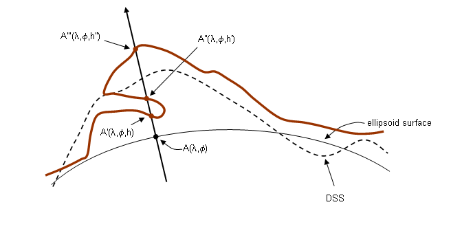
EXAMPLE 3 Figure 4.8 provides an example of an overlap at the boundary of two sets of elevation data provided by two overlapping parts of the reference surface. The coordinate values for the reference surface specified in the currently applicable SRF with its corresponding ORM and vertical offset surface, as specified by the currently applicable srf_context_info field value.
Specifying a multiplicity_rule value of CLOSEST_TO_ORM_CENTRE resolves to point A as the 3D value corresponding to an elevation value of h.
Specifying a multiplicity_rule value of CLOSEST_TO_DSS resolves to point A' as the 3D value corresponding to an elevation value of h'.
Specifying a multiplicity_rule value of FARTHEST_FROM_ORM_CENTRE resolves to point A' as the 3D value corresponding to an elevation value of h'.
See 5.2.6.20 Reference_Surface_Elevation_Select for details on the selection process.
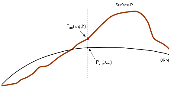
EXAMPLE 4 Given a <DRM CD Surface Location> instance P2D with coordinate values (λ,φ), the third coordinate-component curve of P2D is the line that intersects the ellipsoid at P2D and is orthogonal to the ellipsoid. The intersection of the line with the reference surface R provides the value for the third coordinate-component of the conforming point P3D (see Figure 4.9). The <DRM Reference Surface> instance is associated to the <DRM Geometry Hierarchy> instance that aggregates the objects representing R.
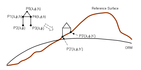
EXAMPLE 5 When representing a house containing exterior walls, conforming points can be used for the lowest vertices of each wall in order for the bottom of the walls to lie on the terrain surface wherever the house is instanced. The coordinates at the bottom of the wall provide only two values as shown with points P2 and P3 in Figure 4.10. The third value of the coordinates is provided by the reference surface yielding points P2’ and P3’.
When an environmental object is placed on a surface, it is sometimes desirable that the environmental object should fit the surface as closely as possible or exactly. The <DRM Conformal Behaviour> class specifies how and where it is necessary to do the extra computation to do the proper fit between the DRM object representing the environmental object and the underlying surface.
An instance of <DRM Conformal Behaviour> also specifies an additional offset to be added to the third value of each conforming point in the geometry of which it is a component.
EXAMPLE 1 A model of a building is to be placed on irregularly sloping terrain.
EXAMPLE 2 A rail fence follows the slope of terrain as it undulates.
Direction information is represented in the DRM by the <DRM Reference Vector> class. A <DRM Reference Vector> instance specifies a 3D unit vector and a reference vector type. The reference vector type defines the semantic meaning of the 3D vector. For a given <DRM Reference Vector> instance, the semantic meaning of the 3D vector may be further qualified by a <DRM Property Value> instance supplied as a component of the <DRM Reference Vector> (see 4.8 Semantic attribution in the DRM for further information).
A <DRM Reference Vector> instance is based at a <DRM Location> instance, which is either a component of the <DRM Reference Vector> instance or is supplied by one of the aggregating DRM objects of the <DRM Reference Vector> instance. The constraint specified in 7.2.61 Required reference vector location defines when the <DRM Reference Vector> instance shall aggregate a <DRM Location> component. For all other cases, a <DRM Location> instance will be inherited.
The 3D unit_vector field of a <DRM Reference Vector> instance specifies a direction in an associated 3D Euclidean SRF that is termed the local tangent frame for the SRF at the supplied or inherited reference <DRM Location> instance. The three tangent vectors of the three coordinate-component curves of the SRF at the reference <DRM Location> instance determine the coordinate axes of the local tangent frame SRF (see 10.5.2 Specification of direction of ISO/IEC 18026 ). If the SRF is based on a linear orthonormal coordinate system, the local tangent frame for the SRF is equivalent to the original SRF except for a translation of the origin. Directions are translation invariant so that in the linear SRF case, the unit_vector may be treated as a direction in the original SRF. The local tangent frame SRF is necessary for 3D curvilinear coordinate system based SRFs including all augmented map projection SRFs. In the curvilinear case, the orientation and/or position of the local tangent frame SRF at one reference <DRM Location> instance is, in general, rotated as well as translated with respect to the local tangent frame SRF at another distinct reference <DRM Location> instance.
For each SRF supported by the SRM that has a curvilinear coordinate system, including SRFs based on augmented map projection SRFTs, a Lococentric Euclidean (LCE) local tangent frame SRF appropriate for each <DRM Reference Vector> instance is constructed. It is this LCE local tangent frame SRF that is used to specify the unit vector information needed for the unit_vector field of the <DRM Reference Vector> instance.
In the Celestiodetic case, if the reference location is on the ellipsoid surface, the LCE local tangent frame SRF coincides with an LTSE local tangent frame SRF. The LTSE local tangent frame SRF is constructed such that it is tangent to the oblate ellipsoid component of the ORM at the reference location, where the SRFT parameters for the LTSE SRF are x_false_origin = y_false_origin = azimuth = h_offset = 0.0. Therefore, for such SRFs, the unit_vector of a <DRM Reference Vector> instance may be interpreted as a vector in the LTSE local tangent frame SRF defined at the position specified by the reference <DRM Location> component of the <DRM Reference Vector> instance.
In the augmented map projection SRF cases, if the reference location is on the ellipsoid surface, the construction of the LTSE SRF is the same as the Celestiodetic case except that the SRFT parameters for the LTSE SRF are x_false_origin = y_false_origin = h_offset = 0.0 and azimuth = convergence of the meridian (see 5.8.3.5 Convergence of the meridian of ISO/IEC 18026) at the reference location.
For the two special cases cited above, if the reference location is not on the surface of the ellipsoid but at some ellipsoidal height (that is, the ellipsoidal height is non-zero), the h_offset parameter is set to the ellipsoidal height.
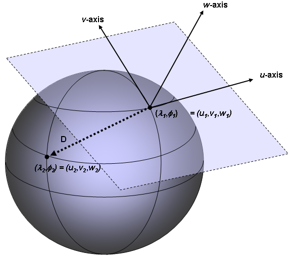
EXAMPLE 1 Given two
points in a celestiodetic SRF with location values (λ1,φ1)
and (λ2,φ2),
the direction from the first point to the second point is as
illustrated in Figure 4.11. The local
tangent frame SRF at (λ1,φ1) is
constructed from the normal tangent vectors of the parallel and meridian at
((λ1,φ1) since the parallel and
meridian are the first two coordinate-component curves at (λ1,φ1).
The tangent to the parallel curve determines the u-axis of the local tangent
frame SRF and the tangent to the meridian curve determines the v-axis of the
local tangent frame SRF. The vector D
pointing from (λ1,φ1) to (λ2,φ2)
is treated as a vector in the local tangent frame SRF at (λ1,φ1).
The
unit_vector
field for a <DRM
Reference Vector> instance with
<DRM CD Surface Location> at (λ1,φ1)
representing the direction pointing from (λ1,φ1)
to (λ2,φ2) is then calculated as
the vector D divided by its length, that is,
the normalization of vector D.
Figure 4.11 — Direction specified with local tangent frame SRF
EXAMPLE 2 In terms of Example 1, the same direction may represented by a second <DRM Reference Vector> instance with a different supplied or inherited reference <DRM Location> instance. In that case, the unit_vector field for the second <DRM Reference Vector> instance may be computed from the unit_vector field for the <DRM Reference Vector> instance of Example 1 by using an SRF operation specified in 10 SRF operations of ISO/IEC 18026.
For a SRF having an ORM that is not an oblate ellipsoid or a sphere, vectors are interpreted in the corresponding Celestiocentric SRF.
Within this part of ISO/IEC 18023, a local SRF is an SRF derived from one of the following SRFTs:
An SRF derived from any other SRF is termed a world SRF.
A <DRM Model> instance can be defined in any SRF. A <DRM Model> instance may be instantiated into another <DRM Model> instance or into a <DRM Environment Root> instance. If a <DRM Model> instance is defined in a world SRF, it can only be instantiated in the DRM object hierarchy of a <DRM Environment Root> instance if there exists a transformation from the model SRF to the target SRF subject to the constraints specified in 7.2.25 <DRM Model> SRF. 10 SRF operations of ISO/IEC 18026 specifies available transformations.
A <DRM Model> instance defined with a local SRF can be instantiated in the DRM object hierarchy of a <DRM Environment Root> with any SRF defined. In this case, an instance of <DRM World Transformation> is used to specify a transformation from the local SRF of the <DRM Model> instance to the target SRF of the <DRM Environment Root> instance.
A <DRM Transformation> instance
allows a <DRM Model> instance to be defined in a local SRF and then instantiated in
another SRF, either a world SRF or another local SRF. A <DRM Model>
instance can be translated, scaled, and/or rotated as part of the instantiation
process. If the model SRF and the target SRF of the other model or environment
root are both derived from a LOCAL_SPACE_RECTANGULAR SRFT, the translation,
scale, and/or rotation may be specified by a
<DRM LSR Transformation>.
Otherwise, the
<DRM World 3x3> component of the
<DRM World Transformation>
instance specifies the rotation and/or scaling data while the <DRM
Location> component of the
<DRM World Transformation>
specifies the translation. If necessary, a local tangent frame shall be
constructed in which to apply the transformation specified by a
<DRM World Transformation>
instance (see 4.7.5 Direction).
A <DRM World Transformation> instance is used only to instantiate a <DRM Feature Model Instance> or <DRM Geometry Model Instance> instance into a world SRF or into another local SRF. A local transformation, such as a <DRM LSR Transformation> instance, is used by <DRM Feature Model Instance> or <DRM Geometry Model Instance> instances. A local transformation may be used by <DRM Aggregate Geometry> to construct a composite geometry representation where portions of the geometry representation need to be oriented and positioned to other portions of the geometry representation. A local transformation may be also be used by <DRM Property Grid Hook Point> instances to position and orient <DRM Property Grid> instances with respect to other parts of a geometry representation. In a <DRM LSR Transformation> instance, the steps used in transforming are found in the subclasses of <DRM LSR Transformation Step>. The rotation, scaling, and translation are specified with instances of <DRM Rotation>, <DRM Scale>, and <DRM Translation>, respectively.
When an <DRM Feature Model Instance> instance or <DRM Geometry Model Instance> instance is evaluated, the steps for applying a <DRM World Transformation> component are as follows.
Let MI be a <DRM Feature Model Instance> instance or <DRM Geometry Model Instance> instance.
Let W be the <DRM World Transformation> component of MI.
Let Sm = SRF of local model.
Let Sltf = local tangent frame LCE SRF with origin at the <DRM Location> component of W.
Let Sw = world SRF.Steps:
- If Sm is LOCAL_SPACE_AZIMUTHAL_2D, LOCAL_SPACE_POLAR_2D, or
LOCAL_SPACE_RECTANGULAR_2D, use SRM operations (see 10 SRF Operations of ISO/IEC 18026) to convert all locations and reference vectors to LOCAL_SPACE_RECTANGULAR_3D.- Left multiply all resulting model LSR_3D locations and reference vectors by the 3x3 matrix specified by the <DRM World 3x3> component of W. Renormalize unit vectors, if necessary.
- Identify each location and reference vector in Sm with its corresponding location and reference vector equivalent in Sltf.
- Use SRM operations (see 10 SRF Operations of ISO/IEC 18026) to convert each location in Sltf to a location in Sw.
A <DRM Spatial Extent> instance specifies a bounding surface (if the SRF is a 2D or surface SRF) or a volume (if a 3D SRF) within which the DRM objects representing environmental data are contained. This includes surfaces with area zero and volumes with volume zero.
A <DRM Spatial Extent> instance has two ordered <DRM Location> components, specified in the SRF in which the <DRM Spatial Extent> has been specified. The ordering of these components is semantically significant. The first of these components is termed the minimum location of the spatial extent. The second of these components is termed the maximum location of the spatial extent. 5 Abstract coordinate systems of ISO/IEC 18026 defines the relationships between coordinate-components. Conceptually, the minimum location can be considered to be the lower left corner and the maximum location can be considered to be the upper right corner of a bounding surface or volume within which all coordinates in the corresponding tree of component relationships are located. Any data that extends beyond the boundaries of the spatial extent is considered invalid.
In the case of an SRF such as geodetic, the coordinate-component values of the maximum location may be either greater than or less than those of the minimum location, depending on the particular region for which spatial domain information is being specified as depicted in the following example:
EXAMPLE Consider the geodetic situation of four points with P1 with a value of (170°, 10°), P2 a value of (-170°, 10°), P3 a value of (170°, -10°) and P4 with a value of (-170°, -10°) as depicted in Figure 4.12. 8 Spatial reference frames of ISO/IEC 18026 specifies the positive direction for both the lines of longitude and lines of latitude. A spatial extent with the first point specified as P3 (170°, -10°) and the second point specified as P2 (-170°, 10°), will define the surface depicted by R1. Conversely, a spatial extent with the first point specified as P4 (-170°, -10°) and the second point specified as P1 (170°, 10°), will define the region depicted by R2 (NOTE R2 is continuous around the back of the ORM). Thus, the location (0°, 0°) is within R2 but not within R1.
Figure 4.12 — Example spatial extents
An instance of <DRM Perimeter Data> specifies the perimeter of the region corresponding to the DRM object of which it is a component.
The n ordered <DRM Location> components of a <DRM Perimeter Data> instance specify the perimeter of the given region by specifying an implicit line segment between each pair of <DRM Location> components i, i+1 for i in the range 1..n-1, where the components are numbered starting at 1. There is a last implicit line segment connecting the nth <DRM Location> component with the first <DRM Location> component so that the <DRM Perimeter Data> specifies a connected boundary. <DRM Perimeter Data> is constrained (see 7.2.53 Non-selfoverlapping perimeter data locations for details) so that the boundary thus specified does not overlap with itself.
EXAMPLE 1 In the case of <DRM Aggregate Feature> or <DRM Aggregate Geometry>, the aggregate represents some aspect or aspects of the region in question.
EXAMPLE 2 In the case of <DRM Sound Instance>, the meaning is more specialized (see 4.15.6 Sound for details).
EXAMPLE 3 <DRM Perimeter Data> instances also occur as link objects in a perimeter-related organization (see 4.13.8 Perimeter for details of its usage).
The semantics of how a <DRM Perimeter Data> instance specifies the perimeter of the given region are the same in all these use cases.
The <DRM Enclosing Volume> class is used to specify instances of volumes in space. Other classes that represent volumetric information include <DRM Volume LOD Data> and <DRM Volume Light Behaviour>. Location and shape data for these classes are specified as for <DRM Enclosing Volume> which is described below.
A <DRM Enclosing Volume> instance is centred at a <DRM Location 3D> instance specified as a component of the <DRM Enclosing Volume> instance. The shape of the volume is specified by a separate component, an instance of one of the concrete subclasses of <DRM Volume Extent>. This design permits a common volume shape to be specified once and reused at many different locations to specify different volumes. The purpose of the volume is determined by the <DRM Enclosing Volume> subclass instanced as a component of the <DRM Aggregate Geometry> instance. Enclosing volumes containing the bounds of the <DRM Aggregate Geometry> are specified as <DRM Bounding Volume> instances. Enclosing volumes used for collision detection are specified as <DRM Collision Volume> instances. Enclosing volumes specifying the volume in which a <DRM Sound> instance is active are specified as <DRM Sound Volume> instances.
<DRM Volume Extent> has three concrete subclasses: <DRM Cylindrical Volume Extent>, <DRM Parallelepiped Volume Extent>, and <DRM Spherical Volume Extent>. <DRM Cylindrical Volume Extent> specifies its major and minor axes as <DRM Reference Vector> components, while the axis lengths and cylinder height are specified by the fields of the <DRM Cylindrical Volume Extent> itself. <DRM Parallelepiped Volume Extent> specifies three ordered <DRM Reference Vector> components as the axes of the parallelepiped, the lengths of which are specified as field values within <DRM Parallelepiped Volume Extent>. <DRM Spherical Volume Extent> specifies the radius of the sphere.
The use of <DRM Reference Vector> instances permits these volume constructs to be subjected to coordinate conversion and transformation without distortion of the volume shapes.
The DRM uses EACs to specify the semantic meaning of some related set of data values where the data type of that set is as defined in ISO/IEC 18025.
An EAC may be specified in the following contexts in the DRM:
For an instance of <DRM Property>, the semantic meaning is specified by a Property_Code value, a data structure that is specified to contain either an EDCS_Attribute_Code or a Variable_Code. The Variable_Code data type supports semantic meanings of attributes that are specific to the DRM. Except for the special cases covered by Variable_Code, the information represented by Property_Code is specified by an EAC.
The set of data values bound to a given instance of <DRM Property> depends upon the concrete subclass involved. <DRM Property> has two concrete subclasses, each of which serves a somewhat different purpose and provides different functionality: <DRM Property Value> and <DRM Property Description>. The common characteristics abstracted by <DRM Property> are discussed above, with the exception of <DRM Property Characteristic>, which is described below.
A <DRM Property Characteristic> instance specifies details about the representation of a property that may include such items as:
A <DRM Property Characteristic> instance appears only as a component of some <DRM Property> instance (or instances). It specifies a value and a semantic meaning for that value, where the semantic meaning is represented by an EDCS_Value_Characteristic_Code, such as TOLERANCE. See 7.2.30 <DRM Property Characteristic> constraints for semantic constraints ensuring that <DRM Property Characteristic> information is meaningful within the context of a <DRM Property> instance.
A <DRM Property Value> instance specifies a single data value, the meaning of which is specified by its meaning field. This data value is specified by its value field, which also specifies the data type of the value.
<A DRM Table Property Description> instance is always a component of a <DRM Data Table> instance, and specifies the meaning of the corresponding set of elements within the cells of the <DRM Data Table> instance. The semantic meaning of a <A DRM Table Property Description> instance is specified by an Element_Type value, a data structure that is specified to contain a value of data type EDCS_Attribute_Code, Index_Code, or Variable Code. The Index_Code and Variable Code data types support semantic meanings of attributes that are specific to the DRM. These two types are constrained regarding the contexts in which they can be used so that they convey semantically valid data.
EXAMPLE The Index_Code value DATA_TABLE_COMPONENT is constrained by 7.2.43 Index codes within tables to appear only within the context of a <DRM Data Table> instance with appropriate characteristics.
A <A DRM Table Property Description> instance also specifies the data type of the data, but the data itself is contained by the cells of the <DRM Data Table> instance. See 4.9 Data tables for further details.
Within the scope of a <DRM Aggregate Feature> or <DRM Aggregate Geometry> instance, many <DRM Property Value> instances may appear that specify values of the same property for different locations, but subject to a common set of constraints, such as a common measurement error, or (collectively) minimum or maximum value.
This information can be provided by an instance of the class <DRM Property Description>. Such an instance of <DRM Property Description> serves to provide context for all <DRM Property Value> instances within the scope of a <DRM Aggregate Feature> or <DRM Aggregate Geometry> of which the <DRM Property Description> is a component, ensuring that the <DRM Property Value> meaning values match that of the <DRM Property Description>.
EXAMPLE 1 Consider a <DRM Property Description> specifying a meaning of WIND_SPEED and a <DRM Property Characteristic> specifying a TOLERANCE value. The information being provided is that <DRM Property Value> instances falling within the scope of that <DRM Property Description> and having the same meaning of WIND_SPEED also have the given TOLERANCE value.
In addition, <DRM Property Description> may have qualifying <DRM Property Value> components that apply to all <DRM Property Value> instances within that scope that have matching meaning field values.
EXAMPLE 2 In a <DRM Aggregate Geometry> instance containing many <DRM Polygon> instances that specify different EMISSIVITY values, the aggregate can contain a single <DRM Property Description> component specifying the EM_BAND.
The DRM uses ECCS to specify the semantic meaning assigned to a collection of DRM objects within the environment.
An ECC may be specified in the following contexts in the DRM:
For <DRM Classification Data>, <DRM Environmental Domain Summary>, and <DRM Reference Surface> instances, the ECC specified is subject to qualification by <DRM Property Value> components, as discussed in 4.8.2.2 Qualification.
The details of the specific interpretation of an ECC depend on the context in which it appears. In the case of a <DRM Classification Data> instance, the tag field specifies the semantic meaning of the DRM object to which the <DRM Classification Data> instance is being applied. This is the most common usage of ECCs, but there are classes that use ECCs for summary or identification purposes rather than to specify the semantic meaning of instances of the classes in which the ECCs are specified.
The environmental_domain field of a <DRM Environmental Domain Summary> instance specifies an ECC that signifies a particular environmental domain is being represented in the given transmittal.
In a <DRM Reference Surface> instance, the classification field specifies that only the geometry in the associated <DRM Geometry Hierarchy> instance matching the given classification is used in resolving coordinate values for <DRM Location 2D> and <DRM Location Surface> instances.
The component_data_table_ecc of a <DRM Table Property Description> instance is used to identify a specific <DRM Data Table> instance being referenced, rather than classifying the <DRM Table Property Description> instance itself.
The final case is that of the texel data of a <DRM Image> instance, where the value of the image_signature field is EDCS_CLASSIFICATION_CODE. In this type of <DRM Image> instance, each texel is an ECC, so that the <DRM Image> instance, when mapped to a specific spatial region, can indicate the classification of various environmental entities in that region.
A <DRM Classification Data> instance specifies the semantic meaning of the DRM object to which the <DRM Classification Data> instance is being applied. This semantic meaning may be further qualified by the presence of <DRM Property Value> components of the <DRM Classification Data> instance that, if present, supply more specific information regarding the semantic meaning being specified.
EXAMPLE A <DRM Classification Data> may specify that the object being classified is a BRIDGE, and may have a <DRM Property Value> component further specifying that the BRIDGE_DESIGN is SUSPENSION. A classification with related attributes is termed a qualified classification.
The DRM provides the capability of expressing relationships between environmental objects by providing the ability to express relationships between their representations. A <DRM Base Association Data> instance specifies the semantic meaning of the association relationship with which it is bound. Consequently, relationships can be expressed between environmental objects represented as instances of concrete subclasses of <DRM Feature Representation>, <DRM Geometry Representation>, or both.
Relationships between representations are of two categories: spatial relationships and functional relationships. An instance of <DRM Base Association Data> will be either a concrete instance of <DRM Base Spatial Association Data> or an instance of <DRM Functional Association Data>. The semantic meaning of a spatial relationship thus represented is expressed by using a concrete subclass of <DRM Base Spatial Association Data> (i.e., either an instance of <DRM Spatial Association Data> or an instance of <DRM Proximity Data>). The meaning field of the instance specifies the spatial relationship being represented.
EXAMPLE For an association relationship between representations of two environmental objects, object_1 and object_2, the meaning field specifies the spatial relationship between object_1 and object_2. If none of the points in object_1 are also in object_2, an association between their representations specified by a <DRM Spatial Association Data> instance that they are DISJOINT could be supplied.
A <DRM Proximity Data> instance, in addition to specifying that the two related environmental objects are in proximity to each other, specifies the distance in metres of that proximity. In addition to providing the capability of specifying spatial relationships, <DRM Base Association Data> provides the capability of specifying functional relationships through its subclass <DRM Functional Association Data>. Relationships supported by this mechanism include CONTROLS, CONTROLLED_BY, and relationships that specify the existence of forces between the two environmental objects, such as SUPPORTS and SUPPORTED_BY.
NOTE Two representations may have more than one relationship with one another including having various spatial relationships in addition to functional relationships.
The abstract <DRM Data Table> class specifies an n-dimensional array of data cells. This cell data is distinct from the DRM fields of the <DRM Data Table> class and is accessed through the specialized API functions, 8.3.23 GetDataTableData and 8.3.65 PutDataTableData.
The number of dimensions of the cell data array is determined by the number of ordered <DRM Axis> components aggregated by a given <DRM Data Table> instance. The axis_value_count field of each <DRM Axis> component specifies the number of cells in its corresponding dimension. The combination of the axis_value_count field values defines the extents of a <DRM Data Table> instance. Subsections of a <DRM Data Table> instance’s cell data are termed subextents. The order of the cell data is determined by the ordered <DRM Axis> components with the data corresponding to the final <DRM Axis> component varying the most.
EXAMPLE 1 A <DRM Data Table> instance of subclass <DRM Property Grid> with one <DRM Regular Axis> instance as specified in Figure 4.13 has ten cell values, subextents from [0] to [9], and the data cell layout given in Figure 4.14.
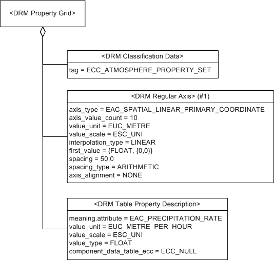
Figure 4.13 — Precipitation rate
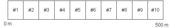
Figure 4.14 — Precipitation rate cell data layout
EXAMPLE 2 A <DRM Property Grid> instance with two <DRM Regular Axis> instances as specified in Figure 4.15 would have 50 cell data values, subextents from [0,0] to [9,4], and of the data cell ordering as shown in Figure 4.16.
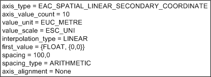
Figure 4.15 — Terrain data
Figure 4.16 — Terrain data cell data layout
Each cell in a data table may contain one or more properties. The ordered list of properties is termed a data table signature. This data table signature is constituted from the ordered list of <DRM Table Property Description> components associated with the <DRM Data Table> instance. A <DRM Table Property Description> instance in the data table signature describes a property contained in the cell data. It specifies the property’s meaning, unit of measure, and data type. The dimensions and data table signature do not fully describe the intended meaning of the overall <DRM Data Table> instance. For that, a <DRM Classification Data> component is provided for each <DRM Data Table> instance.
The cell data for a <DRM Data Table> instance is represented by an array of values of data type Data_Table_Data. Each element of type Data_Table_Data in the array represents the array of property values for the cells of the <DRM Data Table> instance. Since the cell data may be arbitrarily large and consequently pose practical problems for access and storage, the 8.3.23 GetDataTableData and 8.3.65 PutDataTableData functions are provided to extract and insert portions of cell data. Cell data may be accessed by individual properties and/or by a spatial subextents as specified by the extents field which is of data type Data_Table_Data.
When environmental data consists of point-sampled representations of environmental objects in a single SRF, the environmental data can be organized into a collection of spatial locations. In the DRM, such collections can be represented by a <DRM Data Table> instance. The <DRM Property Grid> class is used to specifies a <DRM Data Table> instance containing at least one spatial <DRM Axis> component that describes the point-sampled environmental data. <DRM Property Grid> instances can be used to represent lines, surfaces, or volumes that are point-sampled. As a result, a <DRM Property Grid> instance used with a <DRM Property Grid Hook Point> instance is considered a geometry representation. The <DRM Property Grid> instance uses its srf_context_info field to specify the SRF in which the environmental data was sampled and in which the cell locations form a grid of coordinates. Such a collection of environmental data is termed to have the property griddedness. Other environmental data can be specified for each cell of a <DRM Property Grid> instance.
NOTE In general, griddedness is not preserved if the SRF is changed.
A <DRM Property Grid> instance specifies:
The coordinate data is specified by the intersections of the gridlines specified by its <DRM Axis> components, specifically those <DRM Axis> components that specify spatial information. In the case where multiple <DRM Property Grid> instances contain cell data for the same location and the same property, a <DRM Grid Overlap> instance is used to resolve the data ambiguity.
The <DRM Property Grid Hook Point> class is a subclass of <DRM Geometry Hierarchy> that ties an instance of <DRM Property Grid> to a spatial location within its referenced geometric context. This is an analog to a <DRM Geometry Model> instance referenced at a spatial location using an instance of <DRM Geometry Model Instance> that provides a <DRM Transformation> component. A <DRM Property Grid Hook Point> instance specifies the spatial location as a <DRM Location> component, while a <DRM Property Grid> instance specifies which of its cells corresponds to that location. A <DRM Property Grid> instance specifies its own SRF. This may or may not match the SRF in which the <DRM Property Grid> instance is contained. The spatial_axes_count field specifies how many of the ordered <DRM Axis> components of a given <DRM Property Grid> are spatial, in accordance with the 7.2.63 Spatial axis constraints constraint.
EXAMPLE If a <DRM Property Grid> instance specifies its srf_context_info as Mercator Augmented 3D, there can be no more than one “x” axis, no more than one "y" axis, and no more than one "z" axis.
The cell corresponding to the <DRM Location> component of a <DRM Property Grid Hook Point> instance has indexes on the three or fewer spatial axes specified by the location_index field. The location_index field is not required to specify a point that actually lies within the boundaries of the grid. Thus, several neighbouring <DRM Property Grid> instances may be offset from the same <DRM Property Grid Hook Point> instance.
The <DRM Property Table> class is used to store tabular data that is not spatially aligned. A <DRM Property Table> instance may aggregate other <DRM Property Table> instances as ordered components that are then referenced in the cells of the table by an index into the list of components. <DRM Property Grid> instances cannot be referenced in this way by a <DRM Property Table> instance because the <DRM Property Table> instance provides no spatial location to tie the location_index of the <DRM Property Grid> instance to the instancing SRF.
Attributed data is used throughout the DRM. To fully specify a data value, its meaning and data type are required. If the data type is numeric, a scaled unit of measure is also required. The data table signature of a <DRM Data Table> cell needs this information for each data item.
A <DRM Table Property Description> instance represents a data table signature item in a <DRM Data Table> instance. In addition to the fields inherited from <DRM Property>, <DRM Table Property Description> has a value_type field. All entries in a <DRM Data Table> instance corresponding to a given <DRM Table Property Description> instance have the same value_type, unit, and scale.
In addition, the cells of a <DRM Data Table> instance may reference other <DRM Data Table> instances. In this case, all the data in the referenced <DRM Data Table> instance is represented by the referencing cell. The referenced <DRM Data Table> instance is termed a component data table. This component data table may exist as a direct component of the referencing <DRM Data Table> instance or as a component of a <DRM Data Table Library> instance.
For data table signature items that refer to component data tables, the meaning field of the applicable <DRM Table Property Description> instance is set to the appropriate Index_Code, either DATA_TABLE_COMPONENT or DATA_TABLE_LIBRARY, indicating that the data table's cell values contain an index. For each cell in the referencing data table, the index value indicates which component data table is represented by the cell.
However, a <DRM Data Table> instance may have multiple data table signature items per cell and each may reference a different set of component data tables. Consequently, the set of component data tables that are referenced with a signature item shall all have the same ECC specified in a <DRM Classification Data> component. This ECC shall be distinct from any other ECCs for other component data tables. The signature item determines which set of component data tables to index using the component_data_table_ecc field of the <DRM Table Property Description> instance.
Two of the concrete subclasses, <DRM Regular Axis> and <DRM Irregular Axis>, specify mechanisms for handling interpolation. Interpolation is used to find the value of a data point between the tick marks of the data. The interpolation methods are specified in 5.2.7.24 Interpolation_Type and include values for no preference and to disallow interpolation. The interpolation methods have specific requirements with further specification provided through the supplemental_information field of the <DRM Identification> component of the <DRM Data Table> aggregate of the <DRM Axis> instance.
EXAMPLE 1 The interpolation method DIAGONALIZATION requires 2D data and a data cell element of EA GRID_DIAGONALIZATION.
EXAMPLE 2 The interpolation method KRIGING specifies weighting values that are calculated by deriving the function of the data variogram and evaluating this function over the set of points in the data (see [OLIVER]). If other weighting values are to be used, they are specified in the supplemental_information field of a <DRM Identification> instance.
As a <DRM Table Property Description> instance represents a signature item in a <DRM Data Table>, the signature may be further qualified by the presence of <DRM Property Value> components of the <DRM Table Property Description> instance. If present, these <DRM Property Value> components supply more specific information regarding the signature represented by the <DRM Table Property Description> instance.
EXAMPLE A <DRM Table Property Description> instance may specify a signature item corresponding to the EA HIGH_CLOUD_TOP_LEVEL (see ISO/IEC 18025). This EA requires a vertical reference specified by the related EA ATM_VERTICAL_REFERENCE. By associating a <DRM Property Value> instance containing the enumerated value of the appropriate ATM_VERTICAL_REFERENCE, the HIGH_CLOUD_TOP_LEVEL is fully specified.
The <DRM Axis> class abstracts the common characteristics of its concrete subclasses. Each <DRM Axis> instance specifies:
The <DRM Axis> class has four concrete subclasses:
For an instance of a concrete subclass of <DRM Axis>, the value of the axis_type field is specified by an EDCS_Attribute_Code value and specifies the semantic meaning of the tick marks for that axis. In the case of a <DRM Regular Axis> instance, this applies to the first_value and spacing fields; in instances of the other subclasses, it applies to an explicit array of axis values. The <DRM Axis> subclasses that represent numeric data have value_unit and value_scale fields that determine an unambiguous meaning for the numeric data. The values are constrained to be consistent with the axis_type (see 7.2.39 General axis constraints for details).
Each of the four concrete subclasses is discussed in more detail below.
A spatial <DRM Axis> instance is a <DRM Axis> instance with one of the following as the value of its axis_type field:
For
angular coordinates, such as latitude and longitude, EAC_SPATIAL_ANGULAR_PRIMARY_COORDINATE and
EAC_SPATIAL_ANGULAR_SECONDARY_COORDINATE;
A spatial <DRM Axis> instance shall appear only as a component of a <DRM Property Grid> instance, as specified in 7.2.63 Spatial axis constraints.
For any SRF,
The primary, secondary, and tertiary components for each SRF are specified by the corresponding record type in 11.9.7 Coordinate structures of ISO/IEC 18026.
The designation of a <DRM Axis> instance's axis_type value as primary, secondary, or tertiary is independent of the order in which that <DRM Axis> instance is attached to a <DRM Property Grid> instance.
EXAMPLE Consider a <DRM Property Grid> instance G specified in a 3D CD SRF, in which the data provider is supplying EAC_TERRAIN_ELEVATION data for a region. The spatial <DRM Axis> components are EAC_SPATIAL_ANGULAR_PRIMARY_COORDINATE, which for CD is longitude, and EAC_SPATIAL_ANGULAR_SECONDARY_COORDINATE, which for CD is latitude. The data provider who is creating G in this case is specifying the grid in the order (latitude, longitude), so the first <DRM Axis> component of G is that with axis_type EAC_SPATIAL_ANGULAR_SECONDARY_COORDINATE, while the second <DRM Axis> component of G is that with axis_type EAC_SPATIAL_ANGULAR_PRIMARY_COORDINATE. The EAC_TERRAIN_ELEVATION information is specified by a <DRM Table Property Description> component of G having meaning = {ATTRIBUTE, {EAC_TERRAIN_ELEVATION}}.
The <DRM Regular Axis> class is used to specify a numerical axis that has constant spacing between the axis values. The axis values are called tick marks. To specify the tick marks, a <DRM Regular Axis> instance specifies the starting value (first_value), whether arithmetic or geometric spacing is being used (spacing_type), and the spacing itself (spacing). It also specifies value_unit and value_scale fields that assign a unit of measurement to the tick mark values.
The notion of equal spacing applies to both arithmetic and geometric spacing. If ARITHMETIC is specified, the kth tick mark value is:
tick(k) = first_value + (k × spacing)
If GEOMETRIC is specified, the kth tick mark value is:
tick(k) = first_value × (spacingk)
where first_value shall be non-zero.
When a <DRM Regular Axis> instance is used to represent a continuous value, interpolation could be required. As a result, the preferred interpolation method is provided by the interpolation_type field entry of the <DRM Regular Axis> class. The interpolation methods are specified in 5.2.7.24 Interpolation_Type. If there is no preferred interpolation method, interpolation_type shall have value NOT_SUPPLIED. Data not appropriate for interpolation shall set interpolation_type to DISALLOWED. Spatial axes are not permitted to disallow interpolation, although a data provider may indicate that a preferred interpolation method is not supplied.
EXAMPLE Consider a <DRM Property Grid> instance with one <DRM Regular Axis> component that has first_value = 0, spacing = 100, spacing_type = ARITHMETIC, value_unit = METRE, and value_scale = UNI. The data values at 0 metres, 100 metres, 200 metres, ... are provided within the data of the <DRM Property Grid> instance, but the value at 50 metres or 150 metres is not. If these values are to be determined, they shall be interpolated from the existing data. If interpolation_type = DISALLOWED, the data cannot be determined. If interpolation_type = NOT_SUPPLIED, there is no preferred interpolation method and any method can be used. If interpolation_type = LINEAR, the slope of the best line fitting the data is determined and used to interpolate the data point. Thus, given M = slope of the line, V = the data value at point P and V = P × M.
A spatial axis is a <DRM Axis> instance that describes sampling along one of the components of an SRF. When a <DRM Regular Axis> instance represents a spatial axis as a component of a <DRM Property Grid> instance, the values of the axis are relative to the <DRM Location> components of the <DRM Property Grid Hook Point> instance. The <DRM Property Grid> aggregate of the <DRM Regular Axis> instance specifies which tick mark on the axis will correspond to the <DRM Location> component of the <DRM Property Grid Hook Point> instance using the location_index field of the <DRM Property Grid> instance.
The essential difference between <DRM Regular Axis> and <DRM Irregular Axis> is that the former uses regular spacing to specify its tick marks and the latter does not. The tick marks of a <DRM Irregular Axis> instance are specified explicitly in the axis_value_array field. The number of values in the axis_value_array field is specified by the axis_value_count field, which also indicates how many tick marks are represented along the axis. Further constraints on the contents of the axis_value_array can be found in 7.2.39 General axis constraints. It also specifies value_unit and value_scale fields that assign a unit of measurement to the tick mark values.
The interpolation_type field specifies the interpolation method as described for regular axes.
If a <DRM Irregular Axis> instance is used as a spatial <DRM Axis> instance within a <DRM Property Grid> instance, the values within axis_value_array are all offsets from the location corresponding to the location_index of the grid. For any particular spatial axis of a grid, the kth tick coordinate value is:
v + axis_value_array[k]
where k ranges from zero to axis_value_count-1.
A <DRM Enumeration Axis> instance is constrained to specify an axis_type corresponding to an EAC that is bound to a set of EECs, from which its tick marks are supplied as its axis_value_array.
<DRM Interval Axis> specifies an axis whereby the axis values corresponding to the tick marks are specified as ranges. The axis_interval_value_array will contain axis_value_count entries where all entries are provided as signed or unsigned integers or as floating point numbers. The interval entries shall not overlap and shall satisfy 7.2.39 General axis constraints. It also specifies value_unit and value_scale fields that assign a unit of measurement to the tick mark values.
<DRM Geometry Representation> is an abstract DRM class for which an instance of one of its concrete classes represents an entity in the environment, or an organized collection of such entities, in a manner intended to approximate the physical extent and characteristics of that entity so that it can be presented in terms of a given sensor domain in a realistic manner. Often, but not always, this is in terms of visual representation.
<DRM Geometry Representation> includes, but is not limited to, the concepts of:
<DRM Geometry Representation> also includes the concept of <DRM Property Grid Hook Point> instances used to reference tables, wherein various properties of an entity have been systematically sampled.
A <DRM Geometry Hierarchy> class instance represents a hierarchically organized collection of concrete instances of <DRM Geometry Representation> subclasses. <DRM Geometry Hierarchy> is abstract, and has three subclasses: <DRM Geometry Model Instance>, <DRM Aggregate Geometry>, and <DRM Property Grid Hook Point>.
<DRM Geometry Model Instance> provides a mechanism for referencing the <DRM Geometry Model> component of a <DRM Model> instance. <DRM Geometry Model Instance> is covered in 4.14.2.2 Instancing.
<DRM Aggregate Geometry> and <DRM Property Grid Hook Point> are described below.
A <DRM Aggregate Geometry> instance specifies a collection of <DRM Primitive Geometry> or <DRM Geometry Hierarchy> instances, organized according to some organizing principle specific to the particular subclass of <DRM Aggregate Geometry> being considered as described in 4.13 Organizing principles. Each of the concrete subclasses of <DRM Aggregate Geometry> is covered under the corresponding organizing principle.
A <DRM Property Grid Hook Point> instance specifies the connection between the SRFs of one or more <DRM Property Grid> instances and that of the <DRM Property Grid Hook Point> instance itself, where the <DRM Property Grid> instances are components of the <DRM Property Grid Hook Point> instance.
EXAMPLE Consider a <DRM Property Grid> instance G as shown in Figure 4.17. This instance specifies N spatial <DRM Axis> components, where N is the value of the spatial_axes_count field of G and is between 1 and 3 inclusive. G also has a location_index field specifying an intersection in grid space of the spatial <DRM Axis> data; that is, specifying a position in the SRF of G.
When G is referenced as a component of a <DRM Property Grid Hook Point> instance H, H specifies a <DRM Location> instance L in the SRF in which H is specified. The semantic relationship is that L corresponds to the position in G’s SRF specified by G’s location_index information.
The <DRM Primitive Geometry> class specifies the smallest data elements that can be used to represent environmental objects. The <DRM Primitive Geometry> class is an abstract class with five subclasses.� All instances of these subclasses are aggregated by an instance of the <DRM Union Of Primitive Geometry> class. The five subclasses of <DRM Primitive Geometry> specify geometry in the form of:
While individual <DRM Primitive Geometry> instances may represent a single renderable object, multiple instances are typically needed (e.g., when property data is associated with a set of primitives rather than each primitive individually). In this case, the set of related <DRM Primitive Geometry> instances is aggregated in a <DRM Union Of Primitive Geometry> instance. This allows the property data to be associated with the <DRM Union Of Primitive Geometry> instance and apply to all <DRM Primitive Geometry> instances in the container.
A <DRM Point> instance can specify a <DRM Location> instance with various geometric rendering characteristics or a <DRM Location> instance at which specific attributes apply. A <DRM Point> instance may be associated with an optional <DRM Light Rendering Properties> instance, in which case it is said to represent a light point. A <DRM Point> instance may be used to represent the appearance of any environmental entity that is so small from the viewpoint of an observer that it may be considered as a point. An instance of <DRM Geometric Centre> may be used to specify a point location that has the meaning specified by the meaning field value.
A <DRM Linear Geometry> instance specifies a linear geometric representation. Such an instance may be optionally associated with a <DRM Light Rendering Properties> instance.
The interpretation of the count field depends on whether a <DRM Light Rendering Properties> component is present for the <DRM Linear Geometry> instance. If a <DRM Light Rendering Properties> component is present, count is the number of evenly spaced light points to be rendered along the <DRM Linear Geometry> instance. If no <DRM Light Rendering Properties> component is present, count is the number of evenly spaced line segments to be rendered along the <DRM Linear Geometry> instance.
The geometric topology is specified with an association from a <DRM Linear Geometry> instance to a <DRM Geometry Edge> instance.
A <DRM Line> instance is an ordered list of two or more <DRM Vertex> instances specifying a sequence of connected straight line segments.
EXAMPLE Consider a <DRM Line> instance representing the outline of a rectangular runway. The <DRM Line> instance aggregates five <DRM Vertex> instances with ordered pairs of <DRM Vertex> instances representing the end points of the four line segments representing the runway outline.
A <DRM Arc> instance specifies a circular arc with the centre specified by the component <DRM Location> instance and with end points specified by the <DRM Vertex> components. The arc segment is from the first <DRM Vertex> component until it intersects the radial line that passes through the second <DRM Vertex> component.
EXAMPLE Consider a <DRM Arc> instance L representing an
arc of lights on one side of a helipad. In this particular example, L has two <DRM Vertex> components, a
count value
of 30, and
suppress_last
has value FALSE. The first and last light points are at
the ends of L, and the remaining light points are evenly spaced between them. L has a <DRM Light Rendering
Properties> component specified with a <DRM Flashing Light
Behaviour> instance, so L is rendered as thirty flashing light points, evenly spaced
between L’s endpoints. The UML for this example is depicted in
Figure 4.18.
<DRM Surface Geometry> is the superclass of a set of <DRM Primitive Geometry> classes that use geometrical representation constructs having area, but no thickness. DRM classes that represent surface geometry include <DRM Polygon> and <DRM Ellipse>.
A <DRM Polygon> instance represents a bounded portion of a plane, specified by a set of three or more ordered <DRM Vertex> components. The order of the <DRM Vertex> components is counterclockwise when viewed from the direction identified by computing the cross product of the vector from the first vertex to the second and the vector from the second vertex to the third. The first <DRM Vertex> instance is not duplicated to also appear as the last <DRM Vertex> instance of the <DRM Polygon> instance. Thus, the segment connecting the last <DRM Vertex> instance to the first <DRM Vertex> instance is only implicitly specified. A <DRM Polygon> instance provides for texture mapping through optional <DRM Image Mapping Function> components and colouring through optional <DRM Colour> instances. The value of the polygon_flags field shall have all applicable set members included for a <DRM Polygon> instance.
<DRM Ellipse> represents an ellipse by specifying the centre of the ellipse as a <DRM Location> component, the major and minor axis lengths as field values, and the directions of the major and minor axes as <DRM Reference Vector> components with the appropriate vector_type values, either MAJOR_AXIS or MINOR_AXIS. These vectors are constrained to be perpendicular to one another in the SRF in which they are specified.
The <DRM Volume Geometry> class abstracts common properties of classes used to specify geometric volumes. The <DRM Volume Geometry> class has two concrete subclasses, <DRM Polyhedron> and <DRM Volume Object>.
The <DRM Polyhedron> class specifies an arbitrary, bounded region of three-dimensional space. The exact volume is specified by a set of four or more <DRM Polygon> components. The set of <DRM Polygon> components shall specify a completely enclosed volume.
The <DRM Volume Object> class specifies a bounded region of three-dimensional space with a regular geometric shape. The geometric shape is specified by one of the following <DRM Volume Extent> subclasses:
The centre of a <DRM Volume Object> instance is specified by the <DRM Location 3D> component. The shape and extent of a <DRM Volume Object> instance is specified by the <DRM Volume Extent> component.
A finite element mesh is a surface or volume tessellated by mesh faces in the form of polygons that has property data associated with the mesh face vertices, the mesh faces, and/or solid elements, if any. The data is homogeneous in the sense that if one vertex (or face or solid element) has a set of property types, all the vertices (or faces or solid elements) will have the same set of property types. Since the <DRM Finite Element Mesh> class can represent surface or volume data, it is considered a geometry representation. Because of the homogeneity of the data and since such data is organized as a table, a <DRM Finite Element Mesh> instance uses a <DRM Mesh Face Table> instance to efficiently represent a finite element mesh. Finite element meshes are often used as input data for computational environment models.
A mesh surface consists of a finite set of faces that approximates and partitions a smooth surface or volume. A face is a polygon that may have one or more interior rings. An interior ring is a polygon contained by, and co-planar to, the exterior polygon of a face. Mesh vertices represent the endpoints of the faces where they meet adjacent mesh faces and also represent the endpoints of the faces’ interior rings.
Four DRM classes (or their concrete subclasses) are used to represent a mesh surface:
Each vertex in the mesh surface is represented with a <DRM Vertex> instance that is an ordered component of a <DRM Finite Element Mesh> instance. <DRM Vertex> aggregates concrete instances of <DRM Location> and also any relevant attribute information that may be associated with the vertex. A <DRM Mesh Face Table> component of the <DRM Finite Element Mesh> instance specifies all face information for the mesh. While the fields specify the number of faces in the mesh and the maximum number of vertices needed to specify a face, the actual description of the faces is specified in a two-dimensional mesh face table that is accessed through the API functions, 8.3.30 GetMeshFaceTableData and 8.3.68 PutMeshFaceTableData.
The dimensions of the mesh face table are specified by mesh_face_count (rows) by maximum_vertices_per_face (columns). The table values are non-negative values, prepresenting indexes into the ordered <DRM Vertex> components of a <DRM Finite Element Mesh> instance. Thus, a face in the mesh surface is defined by a row in the mesh face table that specifies a list of vertices that specify a face and its interior rings. If a face has no interior rings, its row in the mesh face table is simply a list of vertex indexes with zero values in any unused columns. If a face has an interior ring, the vertex indexes for the ring’s vertices are listed after the face’s vertices and one delimiting zero index. Other interior rings may follow the first with a zero index separating each. Interior rings shall not overlap either with each other or with the boundaries of the parent mesh face. Each mesh face shall list the vertices in the same order as specified for <DRM Polygon>. Interior rings shall be listed in the opposite order.
EXAMPLE 1 Figure 4.19 illustrates a mesh surface with three faces, one with an interior ring:
This is represented by the following mesh face table depicted in Table 4.5:
Table 4.5 -- Mesh face table for Figure 4.19
|
Mesh face table | Vertices | |||||||
|---|---|---|---|---|---|---|---|---|
| 1 | 2 | 3 | 4 | 5 | 6 | 7 | 8 | |
| 1 (Mesh Face A) | 1 | 2 | 9 | 10 | 0 | 0 | 0 | 0 |
| 2 (Mesh Face B) | 2 | 8 | 9 | 0 | 0 | 0 | 0 | 0 |
| 3 (Mesh Face C with ring) | 2 | 3 | 4 | 8 | 0 | 5 | 6 | 7 |
A <DRM Mesh Face Table> instance may optionally contain face adjacency information in a separate table called the adjacent face table. The presence of the adjacent face table is specified with the Boolean field adjacent_face_table_present. This table has the same dimensions as the mesh face table. The values in the table are positive integer values that specify face indexes that represent the row in the mesh face table. In general, the table value (i, j) represents the face that is adjacent to the ith face through the edge from vertex j to vertex j+1. If the (j+1)th vertex is a zero, the meaning is the first vertex in the row. If there is no adjacent face or if the vertex represents a ring vertex or a zero, the table value shall be zero.
EXAMPLE 2 Table 4.6 contains the adjacent face table for the example depicted in Figure 4.19:
Table 4.6 — Adjacent face table for Figure 4.19
|
Adjacent face table | Vertices | |||||||
|---|---|---|---|---|---|---|---|---|
| 1 | 2 | 3 | 4 | 5 | 6 | 7 | 8 | |
| 1 (Mesh Face A) | 0 | 2 | 0 | 0 | 0 | 0 | 0 | 0 |
| 2 (Mesh Face B) | 3 | 0 | 1 | 0 | 0 | 0 | 0 | 0 |
| 3 (Mesh Face C with ring) | 0 | 0 | 0 | 2 | 0 | 0 | 0 | 0 |
<DRM Feature Representation> is an abstract DRM class for which an instance of one of its concrete classes is used to represent an entity in the environment, or an organized collection of such entities, that specifies the properties of the entity in terms of its spatial connectivity.
A <DRM Feature Representation> instance is either a <DRM Primitive Feature> instance or a <DRM Feature Hierarchy> instance. A <DRM Primitive Feature> instance directly represents some environmental entity, or some portion of an environmental entity, while a <DRM Feature Hierarchy> instance is an organized collection of such primitives.
<DRM Primitive Feature> has the following concrete subclasses:
Consequently, all three of these classes inherit the formal aggregation, component, and association relationships specified for the <DRM Feature Representation> class as well as those for the <DRM Primitive Feature> class. A concrete instance of a <DRM Feature Representation> subclass may have a <DRM Classification Data> instance as a component, denoting what the particular concrete instance of a <DRM Feature Representation> subclass represents, as well as <DRM Property Value> instances to capture the desired characteristics of that concrete instance of a <DRM Feature Representation> subclass.
An instance of <DRM Point Feature> is used to represent a single environmental object, such as a tree, house, vehicle, or table, in such a way that the spatial information associated with that representation has been abstracted to a single point location. (The examples given earlier in this clause, although not directly mentioned, used a <DRM Point Feature> to represent the tree and building.) The spatial information itself is provided by an associated <DRM Feature Node> instance (see 4.12 Topology).
An instance of <DRM Linear Feature> is used to represent a single environmental object, such as a power line, contour line, or road centreline, in such a way that the spatial information associated with that representation has been abstracted to a linear structure. The spatial information itself is provided by an ordered sequence of one or more associated <DRM Feature Edge> instances (see 4.12 Topology).
Each such <DRM Feature Edge> instance is associated through a link object; specifically, an instance of <DRM Edge Direction> specifying the direction in which that <DRM Feature Edge> is to be interpreted to incorporate it into the sequence.
EXAMPLE Consider a <DRM Linear Feature> representation of a single road that is part of a larger system of roads, where the representation is divided into many segments. The topology of the <DRM Linear Feature> in this example is a sequence of many <DRM Feature Edge> instances, where the <DRM Edge Direction> instances specify the direction (from start to end or end to start) in which each <DRM Feature Edge> is to be interpreted so that the <DRM Linear Feature> expresses the entire sequence as a continuous entity.
A <DRM Linear Feature> is not required to be continuous. It is possible for two <DRM Feature Edge> instances to be specified in sequence for a <DRM Linear Feature> that do not share a common endpoint. This permits the representation of linear entities that are discontinuous, such as a road that is interrupted by some terrain obstacle, such as a lake or crater.
An instance of <DRM Areal Feature> is used to represent either an environmental object or the universe within which all other <DRM Primitive Feature> instances are considered to be located.
If an instance of <DRM Areal Feature> is used to represent an environmental object, it represents a single environmental object, such as a lake, orchard, parking lot, or wall, in such a way that the spatial information associated with that representation has been abstracted to a bounded region. The spatial information itself is provided by one or more associated regular <DRM Feature Face> instances (see 4.12 Topology).
If an instance of <DRM Areal Feature> is used to represent the universe within which all other <DRM Primitive Feature> instances are being specified, the universal field shall be set to TRUE and there shall be only one <DRM Areal Feature> with that value for the universal field per transmittal.
An instance of <DRM Volumetric Feature> is used to represent either an environmental object or the 3D universe within which all other <DRM Primitive Feature> instances are considered to be located.
If an instance of <DRM Volumetric Feature> is used to represent an environmental object, it represents a single environmental object, such as a building, or boulder, in such a way that the spatial information associated with that representation has been abstracted to a bounded volume. The spatial information itself is provided by one or more associated <DRM Feature_Volume> instances (see 4.12 Topology).
If an instance of <DRM Volumetric Feature> is used to represent the 3D universe within which all other <DRM Primitive Feature> instances are being specified, the spatial information itself is provided using one associated universal <DRM Feature_Volume> instance (see 4.12 Topology).
A <DRM Feature Hierarchy> instance is a hierarchically organized collection of concrete instances of <DRM Feature Representation> subclasses. <DRM Feature Hierarchy> is abstract, and has two subclasses: <DRM Feature Model Instance> and <DRM Aggregate Feature>.
<DRM Feature Model Instance> is described in 4.14.2.2 Instancing. It provides a mechanism for referencing the <DRM Feature Model> instance of a <DRM Model> instance.
A <DRM Aggregate Feature> instance specifies a collection of <DRM Primitive Feature> and/or <DRM Feature Hierarchy> instances, organized according to some organizing principle specific to the particular subclass of the <DRM Aggregate Feature> instance being considered. Each of the concrete subclasses of <DRM Aggregate Feature> is covered under the corresponding organizing principle (see 4.13 Organizing principles).
Topology, in the DRM, is used to refer to constructs that provide a mechanism for representing entities in terms of spatial connectivity, such that spatial information that is not relevant to connectivity is omitted from the abstraction.
There are two categories of topological representation in the DRM: feature topology and geometry topology. While there are broad structural similarities between the two, they represent different semantic information. Feature topology represents connectivity information for associated <DRM Feature Representation> instances, and semantically represents connectivity information for the environmental data being represented.
EXAMPLE 1 A feature representation of two roads, where any intersections between the two roads are identified in their representations.
Geometry topology represents connectivity information for associated <DRM Geometry Representation> instances and semantically represents connectivity information specific to the geometric representation itself.
EXAMPLE 2 Two <DRM Polygon> instances in which a common boundary is specified topologically.
Feature topology consists of instances of the subclasses of <DRM Feature Topology>:
These instances are always organized by a <DRM Feature Topology Hierarchy> instance.
Geometry topology consists of instances of the subclasses of <DRM Geometry Topology>:
These instances are always organized by a <DRM Geometry Topology Hierarchy> instance.
A <DRM Feature Node> instance represents a position in space that is significant in terms of its connectivity. This position is significant either because it specifies the topology of a <DRM Point Feature> instance, or because it is used to specify an endpoint for one or more <DRM Feature Edge> instances, or both. A <DRM Feature Node> instance can be considered zero-dimensional in the sense that it specifies position but does not specify the dimensions of the thing being represented.
For a <DRM Feature Node> instance N, the position in space represented by N is the <DRM Location> component of N. N indicates for that <DRM Location> instance:
The concept of levels of topological information is discussed in 4.12.3 Geometry topology.
A <DRM Feature Edge> instance represents a sequence of line segments in space such that the sequence is significant in terms of its connectivity. This information is significant either because it specifies the topology of a <DRM Linear Feature> instance, or because it is used to specify part of a boundary of one or more <DRM Feature Face> instances, or both. A <DRM Feature Edge> can be considered one-dimensional, in the sense that it specifies length but does not specify width or height for the entity being represented.
For a <DRM Feature Edge> instance E, the endpoints of E are specified by its ordered associated <DRM Feature Node> instances, where the first <DRM Feature Node> associate N1 is the starting node and the second, N2, is the ending node. This directionality is utilized when specifying sequences of <DRM Feature Edge> instances to specify higher level constructs. Such higher level constructs are described in 6.2.71 <DRM Feature Edge>. If E is not a straight line between N1 and N2, E will have an ordered collection of <DRM Location> components, so that a non-self-overlapping but connected sequence of line segments is specified between N1 and N2. The only self-overlapping case that may occur is when N1 and N2 are the same <DRM Feature Node> instance and there exist intermediate <DRM Location> components..
The set of <DRM Linear Feature> instances associated with E (if any) can always be determined by examining the associations of E. Depending on the level of topological information being supplied, E may also specify the collection of <DRM Feature Face> instances bordered by E, as associates of E that are ordered counterclockwise when looking along E.
A <DRM Feature Face> instance represents a region in space, not necessarily planar, such that the region is significant in terms of its connectivity. A <DRM Feature Face> can be considered two-dimensional in the sense that it does not specify thickness but does specify a spatial extent.
<DRM Feature Face> has a Boolean field universal that indicates whether the <DRM Feature Face> instance is characterized by having an infinite extent (universal has value TRUE) or a finite extent (universal has value FALSE). A transmittal may have at most one universal <DRM Feature Face> instance for each <DRM Environment Root> instance in the transmittal. Such an instance is termed as the universal <DRM Feature Face> instance. All other <DRM Feature Face> instances are termed regular <DRM Feature Face> instances.
Boundaries of a <DRM Feature Face> instance are specified by using a <DRM Feature Face Ring> instance as described in 4.12.2.3.2 <DRM Feature Face Ring>. A <DRM Face Direction> instance specifies the side of a <DRM Feature Face> instance with which a <DRM Areal Feature> instance is associated.
A <DRM Feature Face Ring> instance specifies a boundary as a sequence of one or more ordered <DRM Feature Edge> instances forming a closed (but not necessarily planar) shape. Each <DRM Feature Edge> instance is associated through a <DRM Edge Direction> instance, specifying whether the <DRM Feature Edge> instance is to be interpreted forwards (start to end) or backwards (end to start) for it to connect with its predecessor and successor in the sequence. The constraints specified in 7.2.20 <DRM Feature_Edge> constraints ensure that the <DRM Feature Edge> instances of a <DRM Feature Face Ring> do not touch except at their endpoints. The semantic information supplied by a <DRM Feature Face Ring> instance depends on its relationship with the <DRM Feature Face> instance for which it forms a boundary. That relationship indicates the type of boundary being specified by the <DRM Feature Face Ring> instance in question.
For a regular <DRM Feature Face> instance, one <DRM Feature Face Ring> instance specifies the explicit outer boundary of that <DRM Feature Face> instance. This <DRM Feature Face Ring> component, termed an external <DRM Feature Face Ring> instance, is specified by the regular <DRM Feature Face> instance as the first of its <DRM Feature Face Ring> components to indicate its role.
The other type of boundary that can be specified by a <DRM Feature Face Ring> instance is an inner boundary for the given <DRM Feature Face> instance. It specifies a hole, a region that is not semantically part of the <DRM Feature Face> instance in question. A <DRM Feature Face Ring> instance specifying an inner boundary is termed an internal <DRM Feature Face Ring> instance, and may be part of an instance of either a regular or a universal <DRM Feature Face> instance. In the case of a universal <DRM Feature Face> instance, all <DRM Feature Face Ring> components are internal, as a universal <DRM Feature Face> has no outer boundary while, for a regular <DRM Feature Face> instance, all <DRM Feature Face Ring> components other than the first are internal.
A regular <DRM Feature Face> instance is characterized by having an explicit outer boundary in the form of an external <DRM Feature Face Ring> instance, and thus having a finite extent. A regular <DRM Feature Face> instance may also have inner boundaries, specified by internal <DRM Feature Face Ring> instances. The first <DRM Feature Face Ring> component of a regular <DRM Feature Face> instance specifies the outer boundary, while the remaining <DRM Feature Face Ring> components (if any) specify any inner boundaries.
EXAMPLE Consider a regular <DRM Feature Face> instance associated with a <DRM Areal Feature> instance that represents the exterior wall of some structure, as indicated by a <DRM Classification Data> instance for the <DRM Areal Feature> instance. If the exterior wall contains windows, one possible representation is to represent the boundary of each window by an internal <DRM Feature Face Ring> instance. Note that the representation may go on to use the edges for each such <DRM Feature Face Ring> instance to specify a separate external <DRM Feature Face Ring> instance, regular <DRM Feature Face> instance, and <DRM Areal Feature> instance for the corresponding window, if desired. The fact that the exterior boundary of one of the windows forms an inner boundary of the wall makes the connection between the window and the wall explicit.
Regular <DRM Feature Face> instances may appear at any level of topology.
Instances of <DRM Feature Face> for which the universal field is set to TRUE only occur for topology level THREE or higher. The concept of levels of topology is represented as field information within the hierarchical organization of topology primitives rather than as part of the primitives themselves, since the level of a topological organization characterizes the quality of that information in terms of completeness and lack of redundancy.
There are currently six levels of feature topology organization:
0. A level ZERO organization contains <DRM Feature Topology> instances, but at least two <DRM Feature Node> instances are specified for the same position in space. <DRM Feature Node> instances are required to be present, but higher level topological constructs may or may not be present.
1. At level ONE, no two <DRM Feature Node> instances shall be specified for the same position in space, but otherwise there are no constraints in addition to those for level ZERO. At least two <DRM Feature Edge> instances intersect or overlap at some position not indicated by a common <DRM Feature Node> instance.
2. At level TWO, in addition to the conditions specified at level ONE, no two <DRM Feature Edge> instances intersect or overlap except where they meet at a common <DRM Feature Node>.
3. At level THREE, in addition to the conditions specified at level TWO, the following conditions are met. Every <DRM Feature Face> instance shall have an association to each <DRM Feature Node> instnace located within it, and likewise every <DRM Feature Node> instance shall have an association to each <DRM Feature Face> instance within which it is located. Most importantly, in the context of an instance of <DRM Feature Face>, at level THREE, the set of regular <DRM Feature Face> instances shall form a complete surface and shall be exclusive and exhaustive; that is, they may meet only at common <DRM Feature Edge> instances. Every <DRM Feature Edge> instance shall form part of the boundary of at least one <DRM Feature Face> instance, and every <DRM Feature Face> instance shall have an association with every <DRM Feature Edge> instance forming part of any of its boundaries.
4. At level FOUR, in addition to the conditions specified by level THREE, the following conditions are met. The <DRM Feature Topology> instances are specified by <DRM Location 3D> instances, and at least one <DRM Feature Edge> instance shall form part of the boundary of more than two <DRM Feature Face> instances.
5. At level FIVE, in addition to the conditions specified by level FOUR, the following conditions are met. At least one instance of <DRM Feature Volume> shall exist. Every <DRM Feature Node> instance associates to the <DRM Feature Volume> instance it is located in, if any. Every <DRM Feature Edge> instance associates to the <DRM Feature Volume> instance it is completely located in, if any. Every <DRM Feature Face> instance associates to the two <DRM Feature Volume> instances that bound it. <DRM Feature Volume> instances may not intersect or overlap one another unless they meet at a common <DRM Feature Face> instance. The set of <DRM Feature Volume> instances shall be exclusive and exhaustive. Exactly one <DRM Feature Volume> instance within the parent <DRM Union Of Feature Topology> instance shall have universal set to TRUE, all others shall have universal set to FALSE.
A detailed specification of the levels of feature topology is contained in 5.2.7.11 Feature_Topology_Level.
Universal <DRM Feature Face> instances exist to support the requirements of level THREE topology. A universal <DRM Feature Face> shall be provided for every context in which level THREE topology is specified. Each <DRM Environment Root> instance has its own topology context. Since every <DRM Feature Edge> is required to bound two <DRM Feature Face> instances, the outer boundary of the entire topological surface formed by the regular <DRM Feature Face> instances requires the presence of a universal <DRM Feature Face>, representing the “universe” outside the topological surface.
Since a universal <DRM Feature Face> consequently has infinite extent, it has inner boundaries as represented by internal <DRM Feature Face Ring> components, but has no outer boundary.
A 3D volume in space that is significant in terms of its connectivity is represented with the DRM classes mentioned in the preceding sections as well as <DRM Feature Volume> and <DRM Feature Volume Shell>.
A <DRM Feature Volume> instance represents a 3D volume in space topologically. The 3D volume may be either infinite (i.e., a universal <DRM Feature Volume> instance) or bounded (i.e., a regular <DRM Feature Volume> instance). In addition, the volume may contain any number of holes. The <DRM Feature Volume Shell> class is used to represent a volume's outer boundary and also the boundaries of its holes.
A <DRM Feature Volume Shell> instance specifies a 3D boundary as a sequence of two or more ordered <DRM Feature Face> instances forming a bounded volume. Each <DRM Feature Face> instance is associated through a <DRM Face Direction> instance, specifying whether the <DRM Feature Face> is facing towards or away from the volume.
A regular <DRM Feature Volume> instance, as identified by having its universal field set to FALSE, is used to topologically represent a solid 3D object that may contain holes. The first <DRM Feature Volume Shell> component represents the outer boundary of the object while inner holes are represented with other optional <DRM Feature Volume Shell> components.
A universal <DRM Feature Volume> instance, as identified by having its universal field set to TRUE, is used to topologically represent an infinite volume. This volume is represented by a set of <DRM Feature Volume Shell> components that represent the only holes in the universal volume. There may be at most one universal <DRM Feature Volume> for each <DRM Environment Root> instance in a transmittal.
The structure of the subclasses of <DRM Geometry Topology> somewhat resembles that of their counterparts in <DRM Feature Topology>, but the connectivity information is specified in terms of the location information embedded in the geometry rather than as components of the topology. Instances of <DRM Geometry Topology> may only be used as components of <DRM Union of Geometry Topology> instances.
A <DRM Geometry Node> instance is always associated with an instance of one of the following:
The location of a <DRM Geometry Node> instance is specified by the <DRM Location> component of the associated <DRM Primitive Geometry> instance.
A <DRM Geometry Edge> instance has two <DRM Geometry Node> associates that topologically represent the starting and ending locations of the edge.
When a <DRM Geometry Edge> instance is associated with a <DRM Linear Geometry> instance, the actual locations of the endpoints represented by the associated <DRM Geometry Node> instances are specified with the first and last <DRM Vertex> components of the <DRM Linear Geometry> instance. A <DRM Geometry Edge> instance may also form part of a <DRM Geometry Face> instance.
A <DRM Geometry Face> instance topologically represents a finite geometric surface. The <DRM Geometry Face> instance is represented with one or more <DRM Geometry Edge> instances. In this case, the locations for the corresponding <DRM Geometry Node> instances are specified by the associated <DRM Polygon> instance. A <DRM Geometry Face> instance may also form part of a <DRM Geometry Volume> instance.
<DRM Geometry Face> is simpler than its counterpart in feature topology. A <DRM Geometry Face> instance F is associated with some collection of <DRM Polygon> instances that form a connected surface, specifying the outer boundary of the surface in question (which may or may not be planar). The <DRM Geometry Edge> instances forming the outer boundary of F shall be specified by <DRM Vertex> instances forming the outer boundary of the polygonal representation being so abstracted.
A <DRM Geometry Volume> instance topologically represents a 3D solid volume. The <DRM Geometry Volume> instance is represented with four or more associated <DRM Geometry Face> instances. The <DRM Geometry Volume> instance is associated to a <DRM Polyhedron> instance that contains the actual location information in its <DRM Polygon> components.
There are fourteen data organizing principles for geometry representation, and ten for feature representation. Each of these is an organizing container that holds one or more data items. Most of the containers (for both feature and geometry) can hold other containers.
The following is a list of the various organizing principles:
Of these, the following concepts organize by spatial relationship:
Each of these organizing principles has at least one formal constraint specifying the semantic constraints that apply to the corresponding <DRM Aggregate Geometry> and <DRM Aggregate Feature> subclasses that embody these organizing principles.
Organizing principles that provide special purpose groupings include:
Other organizing principles include:
Each of these organizing principles is described more fully below.
Each instance of <DRM Aggregate Geometry> and <DRM Aggregate Feature> either strictly complies with the constraints imposed by the organizing principle applicable to the specific subclass it is an instance of, or does not strictly comply. The organizing principle constraint for each specific organizing principle subclass specifies what constitutes strict compliance for that subclass. This part of ISO/IEC 18023 supports either strict or loose compliance to these constraints.
EXAMPLE In a spatial organization defined in terms of boundaries, strict compliance might require that a primitive assigned to a branch associated with a particular boundary be contained completely within that boundary, while non-strict compliance would require only that the primitive overlap the specified region rather than be contained within it.
The strict_organizing_principle field of data type Boolean specifies whether a specific instance of <DRM Aggregate Geometry> or <DRM Aggregate Feature> complies strictly with its organizing principle. A value of TRUE specifies that the given instance meets the criteria for strict compliance for the corresponding subclass. A value of FALSE specifies that the given instance does not meet the criteria for strict compliance. The strict_organizing_principle field allows data consumers to make informed decisions about processing object representations, since it notifies data consumers about what simplifying assumptions can be made about the level of organizing principle compliance being observed.
In any <DRM Aggregate Geometry> or <DRM Aggregate Feature> instance, the possibility exists that a primitive within the organization represented by that instance may appear in more than one branch of the aggregation.
EXAMPLE A <DRM Polygon> instance falling on a cell boundary within a spatial index organization might be assigned to both cells by the data provider responsible for that <DRM Polygon>.
The unique_descendants field of data type Boolean specifies whether each primitive is unique or may be shared. A value of TRUE indicates that each primitive in the aggregation only appears one time. A value of FALSE indicates that each primitive may be shared within the aggregation. This field allows a data consumer to optimize processing if the value is TRUE.
The alternate hierarchy organizing principle provides a DRM mechanism to represent the same set of environmental data using different representations. Organization by alternate hierarchy is supported by the DRM classes <DRM Alternate Hierarchy Related Geometry> for geometry representation and <DRM Alternate Hierarchy Related Features> for feature representation. The alternate_representation_reason field of an instance of the link class <DRM Hierarchy Data> specifies the reason for each specific branch in the hierarchy.
The animation organizing principle represents environmental data as a sequence of animation frames. A <DRM Animation Related Geometry> instance aggregates an ordered set of <DRM Geometry Hierarchy> instances that comprises the sequence of animation frames. The behaviour of the animation sequence is controlled by the ordered <DRM Animation Behaviour> components of a <DRM Animation Related Geometry> instance.
Each <DRM Animation Behaviour> specifies:
The classification related organizing principle groups environmental data by ECC using instances of <DRM Classification Related Features> and/or <DRM Classification Related Geometry>. Each instance of <DRM Classification Related Features> shall have at least one component <DRM Feature Hierarchy> with the ECC specified in an accompanying <DRM Classification Data> link object. Likewise, each instance of <DRM Classification Related Geometry> shall have at least one component <DRM Geoemtry Hiearchy> with the ECC specfied in an accompanying <DRM Classification Data> link object.
The continuous LOD organizing principle provides a mechanism to represent the same environmental object at continuously finer levels of detail using a hierarchy of <DRM Continuous LOD Related Geometry> instances. The root <DRM Continuous LOD Related Geometry> instance in the hierarchy holds the least detailed polygonal representation of the whole environmental object. Each child <DRM Continuous LOD Related Geometry>> in the hierarchy holds polygonal data that represents, at a finer level of detail, all or part of the environmental object represented by its parent.
For sibling <DRM Continuous LOD Related Geometry> instances, the geometry representations shall not overlap except possibly at the edges of individual polygons. At any given level, it is not required that all sibling <DRM Continuous LOD Related Geometry> instances represent the entire portion of the environmental object that is represented by their parent.
The actual geometry for a given <DRM Continuous LOD Related Geometry> is specified by <DRM Polygon> instances contained within a <DRM Union Of Primitive Geometry> component. These <DRM Polygon> instances are not necessarily triangular. The vertex locations for geometry representations at a coarser level of detail are not required to be present in geometry representations at a finer level of detail.
While the geometry of a child <DRM Continuous LOD Related Geometry> instance is considered an alternate representation of part of the parent's representation, the consuming application determines which representation to display at any given time.
The LOD organizing principle provides a mechanism to represent the same set of environmental data by providing equivalent representations at different levels of detail, using instances of <DRM LOD Related Geometry> and/or <DRM LOD Related Features>. The actual alternate representations at the differring levels of detail are contained in instances of <DRM Geometry Hierarchy> and/or <DRM Feature Hierarchy>. The level of detail information is provided in an accompanying <DRM Base LOD Data> link object.
The DRM classes available to be used as link objects to store the level of detail information are:
The <DRM Distance LOD Data> class specifies a level of detail described in terms of distance from the eyepoint to the centre of the object. Instances of <DRM Distance LOD Data> specify the range in metres within which the corresponding instance of <DRM Feature Hierarchy> or <DRM Geometry Hierarchy> is valid, and fade bands at each end of the range that specify the size of the transition from invisible to fully visible (and vice versa) for the corresponding instance of <DRM Feature Hierarchy> or <DRM Geometry Hierarchy>.
The centre of the object to be used for evaluation is provided as a <DRM Location> component of the <DRM Distance LOD Data> link object.
The <DRM Index LOD Data> class specifies an index that indicates the relative level of detail of the associated data. Lower values indicate more detailed versions and higher values indicate less detailed versions.
The <DRM Map Scale LOD Data> class specifies the level of detail based on the map scale of the associated data. The map scale is provided as a float value.
The <DRM Spatial Resolution LOD Data> class specifies the level of detail based on spatial resolution providing both the spatial resolution and the unit of measurement for such resolution.
The <DRM Volume LOD Data> class specifies the level of detail representation based on a volume and whether the data is inside or outside the volume. The centre of the volume is specified by the <DRM Location 3D> component of the link object. The shape of the volume is specified by the <DRM Volume Extent> component of the link object. The class has a single Boolean field value that, if set, specifies that the data within the specified branch is valid inside of the volume. When the flag is not set, the value of the data is valid when outside of the specified volume. The surface of the volume is considered inside the volume.
The octant related organizing principle is represented in the DRM by the <DRM Octant Related Geometry> class for the organization of geometry, and the <DRM Octant Related Features> class for the organization of features. The two classes are constrained by the 7.2.54 Octant related organizing principle constraint to ensure that instances of these classes are semantically valid. In terms of their octant behaviour, <DRM Octant Related Features> and <DRM Octant Related Geometry> have exactly the same organization, so “octant related aggregation”, will be used herein to mean either an instance of <DRM Octant Related Geometry> or an instance of <DRM Octant Related Features>. The notion of octant is analogous to that of a quadrant as discussed in 4.13.9 Quadrant related. The meaning of the octant field is specified in 5.6.2.16 Octant.
An octant corresponds to the spatial data structure notion of a region octree (see [SAMET]) that divides a volume into eight equal-sized octants. However, an octant in this part of ISO/IEC 18023 is not necessarily a classical region octree, in that a SEDRIS data provider is not constrained to organize the entire hierarchy below an octant as smaller and smaller octrees. A data provider may choose to do so, but it is not a requirement.
The region being subdivided into octants is specified by attaching a three-dimensional <DRM Spatial Extent> component to each octant related organizaiton. This <DRM Spatial Extent> component specifies the parallelepiped that is being divided into octants. Every octant related aggregation has between one and eight branches (<DRM Feature Hierarchy> instances in the case of <DRM Octant Related Features>, <DRM Geometry Hierarchy> instances in the case of <DRM Octant Related Geometry>) corresponding to the equal-sized octants into which the region is being partitioned. The <DRM Octant Data> link object for a given branch indicates, via the value of its octant field, which of the eight octants is represented.
Note that an octant related organization is not required to specify a branch for each possible octant. Some data providers may have data that naturally lends itself to octant organization, but which for some reason leaves one or more octants empty.
For consumption of a transmittal in a SRF other than that in which it was specified, 7.2.54 Octant related organizing principle specifies further constraints to ensure that each octant is clearly specified, even if coordinate conversion or transformation is applied to the data. This is necessary, because the notion of size is not invariant under coordinate conversion and transformation. Consequently, each branch of an octant related organization is required to specify an explicit three-dimensional <DRM Spatial Extent>, corresponding exactly to the bounding parallelepiped of the octant represented by that branch.
Since a <DRM Spatial Extent> component specifies a strict boundary, no position information in the scope of its aggregate may lie outside the bounding parallelepiped specified by the <DRM Spatial Extent>. Consequently, the strict_organizing_principle field value of an octant related organization is always TRUE indicating that the octant related organizing principle is strictly obeyed. In addition, since the octants partition the octant’s region and do not overlap, no two branches may have primitives in common, so the unique_descendants field value of an octant related aggregation is always TRUE. A user who does not wish to ensure that the primitives within his or her data always conform strictly to an octant related organization can still organize the data spatially, using a spatial index related organization.
The perimeter related organizing principle provides for spatial organization of environmental data by providing a set of non-overlapping perimeters. This organizing principle is expressed in the DRM by the <DRM Perimeter Related Geometry>, <DRM Perimeter Related Features>, <DRM Perimeter Related Geometry Topology>, and <DRM Perimeter Related Feature Topology> classes. Each of these classes may contain instances of <DRM Geometry Hierarchy>, <DRM Feature Hierarchy>, <DRM Union Of Geometry Topology>, and <DRM Union Of Feature Topology>, respectively, with link objects that are instances of <DRM Perimeter Data>. The perimeter data is stored as <DRM Location> components of the link object. This class shall satisfy the constraint 7.2.53 Non-selfoverlapping perimeter data locations.
The quadrant related organizing principle is represented in the DRM by the <DRM Quadrant Related Geometry> class for the organization of geometry, and the <DRM Quadrant Related Features> class for the organization of features. The two classes are constrained by the 7.2.60 Quadrant related organizing principle constraint to ensure that instances of these classes are semantically valid. In terms of their quadrant behaviour, <DRM Quadrant Related Features> and <DRM Quadrant Related Geometry> have exactly the same organization, so “quadrant related aggregation”, will be used herein to mean either an instance of <DRM Quadrant Related Geometry> or an instance of <DRM Quadrant Related Features>. The notion of quadrant is analogous to that of an octant as discussed in 4.13.7 Octant related.
A quadrant corresponds to the spatial data structure notion of a region quadtree (see [SAMET]), that divides a region into four equal-sized quadrants. However, a quadrant in this part of ISO/IEC 18023 is not necessarily a classical region quadtree, in that a SEDRIS data provider is not constrained to organize the entire hierarchy below a quadrant as smaller and smaller quadrants. A data provider may choose to do so, but it is not a requirement.
To begin specifying a quadrant, the region being subdivided into quadrants shall be specified. This is done by attaching a <DRM Spatial Extent> component to each quadrant related aggregation, specifying the rectangular region being divided into quadrants. Every quadrant related aggregation then has between one and four branches (<DRM Feature Hierarchy> instances in the case of <DRM Quadrant Related Features>, <DRM Geometry Hierarchy> instances in the case of <DRM Quadrant Related Geometry>) corresponding to the equal-sized quadrants into which the region is being partitioned. The <DRM Quadrant Data> link object for a given branch indicates, via the value of its quadrant field, which of the four quadrants is represented. The meaning of the quadrant field is specified in 5.6.2.19 Quadrant.
A quadrant related organization is not required to specify a branch for each possible quadrant. Some data providers may have data that naturally lends itself to quadrant organization, but which for some reason leaves one or more quadrants empty.
EXAMPLE A <DRM Quadrant Related Geometry> representing some area of terrain may include a lake within its boundaries, such that one or more of the quadrants has no non-bathymetric terrain. (Conversely, a <DRM Quadrant Related Geometry> organizing <DRM Property Grid> instances describing various properties of a region of sea water may omit a quadrant because it corresponds to an island.)
To assist the API in consuming a transmittal in an SRF other than that in which it was specified, 7.2.60 Quadrant related organizing principle specifies further constraints to ensure that each quadrant is clearly specified, even if coordinate conversion or transformation is applied to the data. This is necessary, because the notion of size is not invariant under coordinate conversion and transformation. Consequently, each branch of a quadrant related organization is required to specify an explicit <DRM Spatial Extent> instance corresponding exactly to the bounding box of the quadrant represented by that branch.
A <DRM Spatial Extent> component specifies a bounding box such that no position information in the scope of its aggregate may lie outside the bounding rectangle (if the <DRM Spatial Extent> instance is two-dimensional) or bounding parallelepiped (if the <DRM Spatial Extent> instance is three-dimensional). Consequently, the strict_organizing_principle field value of a quadrant related organization is always TRUE, indicating that the quadrant related organizing principle is strictly obeyed. Since the quadrants do not overlap, no two branches may have primitives in common, so the unique_descendants field value of a quadrant related aggregation is always TRUE. A user who does not wish to ensure that the primitives within his or her data always conform strictly to a quadrant related organization can still organize the data spatially, using a spatial index related organization.
The separating plane organizing principle provides for organizing environmental data based on whether the data is on the positive or negative side of a specified plane. The organization is contained within instances of <DRM Separating Plane Related Geometry> that aggregate instances of <DRM Separating Plane Relations> that, in turn, aggregate instances of <DRM Geoemtry Hierarchy> and a component of <DRM Separating Plane>. A <DRM Separating Plane Data> link object provides a Boolean field specifying if an environmental data objects are on the positive or negative side of the plane specified by the <DRM Separating Plane> instance. The separating plane is specified by the three ordered <DRM Location> components. The positive side of the plane is specified to be the side with plane normal pointing towards it and the negative side with the plane normal pointing away from it. The order of the <DRM Location> components is counter clockwise when viewed from the direction identified by computing the cross product of the vector from the first location to the second and the vector from the second location to the third.
The spatial index related organizing principle specifies an aggregation in which each component represents a different rectangular area, termed a tile, within a spatially indexed organization of objects within a transmittal. Each tile is uniquely identified with two indexes contained in the <DRM Spatial Index Data> link object attached to each component.
The spatial index related organizing principle is represented in the DRM by the <DRM Spatial Index Related Geometry> class for the organization of geometry, the <DRM Spatial Index Related Features> class for the organization of features, the <DRM Spatial Index Related Geometry Topology> class for the organization of geometry topology, and the <DRM Spatial Index Related Feature Topology> class for the organization of feature topology. The four classes are constrained as specified in 7.2.64 Spatial index related organizing principle to ensure that instances of these classes are semantically valid. In terms of their spatial index behaviour, all four have exactly the same organization, so the term spatial index related aggregation will be used to refer to an instance of any of the four classes named above.
The state related organizing principle provides representation of the same environmental data with different state values. This is implemented with DRM classes <DRM State Related Features> and <DRM State Related Geometry> that aggregate instances of DRM classes <DRM Feature Hierarchy> and <DRM Geometry Hierarchy>, respectively, through use of <DRM State Data> link objects, where each branch of the aggregation represents a particular state. <DRM State Related Features> and <DRM State Related Geometry> instances have both state_tag and active_state_value fields.
The state_tag field is the EAC that is being used to differentiate the components of the state aggregation. The state is one of a special set of EDCS Attributes that are termed state applicable. See 7.2.65 State related organizing principle for rules on which attributes are considered state applicable. The active_state_value field specifies the default value for the state information. If the given <DRM State Related Features> or <DRM State Related Geometry> instance has a <DRM State Control Link> component, this field is the target of that <DRM State Control Link> instance.
The <DRM State Data> instance stores a value for the specific branch of the same fundamental type as specified by the active_state_value field.
In state related aggregations, the state_tag field specifies the semantic meaning of the related <DRM State Data> field values, as well as that of the active state of the aggregation as a whole. Since EAs that are used as state tags are restricted to those EDCS attributes having percentage or enumerated values, unit and scale information need not be specified. A more detailed explanation relating to the control link mechanism is in 4.16.4 Discrete state control.
The time organizing principle provides a representation of environmental data at different points in time. This is implemented with the DRM classes <DRM Time Related Features> and <DRM Time Related Geometry> that aggregate instances of <DRM Feature Hierarchy> and <DRM Geometry Hierarchy>, respectively, with link objects of <DRM Time Constraints Data>. A <DRM Time Constraints Data> instance contains one component of <DRM Base Time Data> that specifies the type of organization. The data can be organized based on the following types of time data:
These types are specified using the following concrete classes:
<DRM Time Interval> is the superclass of <DRM Absolute Time Interval> and <DRM Relative Time Interval>. <DRM Time Point> is the superclass of <DRM Absolute Time> and <DRM Relative Time>.
The <DRM Time Related Features> or <DRM Time Related Geometry> classes provide a time_data_type field for specifying the type of time data.
<DRM Union Of Geometry Hierarchy> class exists to allow <DRM Geometry Hierarchy> instances to be grouped together where none of the more structured organizing principles is applicable.
EXAMPLE 1 Consider a <DRM Geometry Model> instance representing a building, in which the <DRM Geometry Hierarchy> instance consists of four <DRM Geometry Model Instance> instances of another <DRM Geometry Model> instance representing a wall. Each <DRM Geometry Model Instance> instance has an appropriate <DRM Transformation> component ensuring that it is instanced with the correct position and orientation; no higher level organization is needed. Consequently, the <DRM Geometry Model> instance uses a <DRM Union Of Geometry Hierarchy> instance to aggregate the four <DRM Geometry Model Instance> instances.
The components of a <DRM Union Of Geometry Hierarchy> instance are not required to be homogeneous.
EXAMPLE 2 A <DRM Union Of Geometry Hierarchy> instance may contain both <DRM Property Grid Hook Point> instances and <DRM Union Of Primitive Geometry> instances as components.
The components are required to be unique. That is, a given <DRM Geometry Hierarchy> instance cannot be attached twice as a component of the same <DRM Union Of Geometry Hierarchy> instance. This does not in itself guarantee that none of the <DRM Geometry Hierarchy> components have common primitives; therefore, the field value of unique_descendants is data-dependent.
The <DRM Geometry Hierarchy> components of a <DRM Union Of Geometry Hierarchy> instance are ordered. That is, retrieving the kth <DRM Geometry Hierarchy> component of a given <DRM Union Of Geometry Hierarchy> instance will always result in the same object. The meaning of, or reason for, the ordering, if any, is specified by the ordering_reason field of the <DRM Union Of Geometry Hierarchy> instance.
EXAMPLE 3 If the data provider chose to use the ordering of the <DRM Geometry Hierarchy> components to indicate rendering order rather than using explicit <DRM Rendering Priority Level> instances, ordering_reason would be FIXED_LISTED.
Since a <DRM Union Of Geometry Hierarchy> instance has no organizing principle other than that its descendants are unique and its ordering reason, its strict_organizing_principle field value is always TRUE. For instances where there is no ordering reason,, the ordering_reason field shall be set to NONE.
A <DRM Union Of Primitive Geometry> instance groups an ordered list of <DRM Primitive Geometry> instances. All <DRM Geometry Hierarchy> branches eventually terminate by reaching a <DRM Geometry Model Instance>, a <DRM Property Grid Hook Point>, or a <DRM Union Of Primitive Geometry>, at which point the hierarchical organization transitions into another concept. In the case of <DRM Union Of Primitive Geometry>, a <DRM Union Of Primitive Geometry> exists to connect actual <DRM Primitive Geometry> instances to the rest of the organization of a transmittal; <DRM Primitive Geometry> instances cannot occur in any other context.
The components of a <DRM Union Of Primitive Geometry> are not required to be homogeneous.
EXAMPLE 1 A <DRM Union Of Primitive Geometry> instance may contain both <DRM Polygon> instances and <DRM Point> instances as components.
The components are required to be unique. A given <DRM Primitive Geometry> instance cannot be attached twice as a component of the same <DRM Union Of Primitive Geometry> instance. Consequently, the unique_descendants field value of a <DRM Union Of Primitive Geometry> instance is always TRUE.
The <DRM Primitive Geometry> components of a <DRM Union Of Primitive Geometry> are ordered. Retrieving the kth <DRM Primitive Geometry> component of a given <DRM Union Of Primitive Geometry> shall always result in the same object. The reason for the ordering, if any, is specified via the ordering_reason field of the <DRM Union Of Primitive Geometry> instance.
EXAMPLE 2 If the data provider chose to use the ordering of the <DRM Primitive Geometry> components to indicate rendering order rather than using explicit <DRM Rendering Priority Level> instances, ordering_reason would be FIXED_LISTED.
Since a <DRM Union Of Primitive Geometry> has no organizing principle other than that its descendants are unique and its ordering reason, its strict_organizing_principle field value is always TRUE. For instances where there is no ordering reason, the ordering_reason field shall be set to NONE.
The <DRM Union Of Features> class is the analogue to both <DRM Union Of Geometry Hierarchy> and <DRM Union Of Primitive Geometry>; its components may be either <DRM Feature Hierarchy> instances and/or <DRM Primitive Feature> instances.
The components of a <DRM Union Of Features> instance are not required to be homogeneous.
EXAMPLE 1 A <DRM Union Of Features> instance may contain both <DRM Quadrant Related Features> instances and <DRM Areal Feature> instances as components.
The components are required to be unique. That is, a given <DRM Feature Representation> instance cannot be attached twice as a component of the same <DRM Union Of Features> instance. This does not in itself guarantee that none of the components have primitives in common when <DRM Aggregate Feature> components are present. Therefore, the field value of unique_descendants is data-dependent.
The <DRM Feature Hierarchy> components of a <DRM Union Of Features> instance are ordered. That is, retrieving the kth <DRM Feature Hierarchy> component of a given <DRM Union Of Features> instance will always result in the same object. The meaning of, or reason for, the ordering, if any, is specified by the ordering_reason field of the <DRM Union Of Features> instance.
EXAMPLE 2 If the data provider chose to use the ordering of the <DRM Feature Hierarchy> components to indicate rendering order for any geometry to be derived from the features, ordering_reason would be FIXED_LISTED.
Since a <DRM Union Of Features> instance has no organizing principle other than that its descendants are unique, its strict_organizing_principle field value is always TRUE. For instances where there is no ordering reason, the ordering_reason field shall be set to NONE and similarly for union_reason.
The DRM provides the following mechanisms for sharing data within a transmittal:
Each of these is described below.
A model is specified as a representation of an entity or phenomenon in the environmental data. This could include such items as a tree, a forest, a park bench, a door knob, or a motor vehicle. Furthermore, models can be composed of other models.
EXAMPLE 1 A model of a house could be composed of a set of window models, door models, and wall models.
When a model can stand alone entity in the transmittal, it is termed a root model. If it cannot stand alone, it is termed a component model. When a model is a component model, <DRM Attachment Point> instances can be used to identify where distinct models connect. <DRM Contact Point> instances specify locations where an intersection test should be made to determine if models intersect. <DRM Overload Priority Index> instances specify priority of models for cases in which model complexity cannot be handled by an consuming application.
A model is embodied in the DRM through the class <DRM Model>. This class allows a model to contain both a featurerepresentation and geometry representation.� The feature representation is specified using instances of the <DRM Feature Model> class and the geometry representation is specified using instances of the <DRM Geometry Model> class. Models can be constructed with a specific SRF and have field values to indicate:
A <DRM Model> instance within a <DRM Model Library> instance can contain feature and/or geometry data similar to a <DRM Environment Root> instance. This allows models to be worlds unto themselves. Since a <DRM Model> instance can be instanced within a <DRM Environment Root> instance or another <DRM Model> instance, complex worlds composed of environments containing many <DRM Model> instances can be constructed.
EXAMPLE 2 one method for representing the solar system is to design and describe each of the planets at the desired detail and place them in the <DRM Model Library> instance as individual <DRM Model> instances. Subsequently, each of the planets may be instanced at the appropriate position within the environment (under a <DRM Environment Root> instance). Since a <DRM Model> instance can reference another <DRM Model> instance, each representation of the planets can contain very detailed data, such as trees and buildings.
Models are stored in the transmittal under the <DRM Model Library> component of the <DRM Transmittal Root> instance. These models are instanced into other models or into the hierarchy under a <DRM Environment Root> instance in a transmittal. The DRM allows the instancing of the specific <DRM Geometry Model> or <DRM Feature Model> components of the <DRM Model> instance. To create an instance of the geometric representation of a model, a <DRM Geometry Model Instance> instance is created that associates to the <DRM Geometry Model> instance to be instanced. Likewise, in order to instance the feature representation of a model, a <DRM Feature Model Instance> instance is created that associates to the <DRM Feature Model> instance to be instanced.
When instancing models into local use within the environment, variations to the base model can be assigned using translation, rotation, and scaling, as well as overriding the attributes of the base model.� Overriding attributes of the base model is discussed in 4.16.2 Control links and expressions, while other changes to models are referred to as transformations in this part of ISO/IEC 18023.
There are two purposes for transforming models. The first purpose is to instance into a new SRF and the second is to provide local attributes for models to appear to be unique. The abstract DRM class <DRM Transformation> provides the mechanism to support both of these capabilities. It provides the capability to transform into a new SRF and alter the model using the <DRM World Transformation> class. The DRM also provides for altering models instanced within other models using the <DRM LSR Transformation> subclass of <DRM Transformation>.
The <DRM World Transformation> class specifies a <DRM Location> and a 3×3 matrix, used to transform the model into the non-LSR SRF. The <DRM Location> instance is in a destination SRF, and specifies the position to which the origin of the model is transformed. The 3×3 matrix provides a nine-element matrix containing scaling and rotation where the direction of rotation is determined by the right-hand rule.
The <DRM LSR Transformation> class specifies the transformation to occur when instancing a model in an LSR SRF into another model in an LSR SRF. The transformation is specified by an instance of <DRM Local 4x4> and/or by an ordered set of instances of <DRM LSR Transformation Step>, or both. If both are specified, the instance of <DRM Local 4x4> shall represent the composite of the set of <DRM LSR Transformation Step> instances in compliance with 7.2.24 <DRM LSR Transformation> components.
A <DRM Library> instance serves as a repository for data that may occur many times within the scope of a <DRM Environment Root> instance or <DRM Model> instance. The data is stored once in the <DRM Library> instance, then instanced via references to the <DRM Library> instance rather than replicating the actual data every time the data is used.
The abstract class <DRM Library> has seven concrete subclasses:
In any given transmittal, there can be at most one instance of each of the seven <DRM Library> subclasses.
A <DRM_Colour_Table Library> instance contains instances of <DRM Colour Table Group>.� Instances of this class contain <DRM_Colour Table> instances that, in turn, contain <DRM Primitive Colour> instances. This mechanism supports grouping and reuse of <DRM Primitive Colour> instances throughout a transmittal.
In order to share primitive colours, the DRM provides the class <DRM Colour Index>. Instances of this class have associations to the <DRM Colour Table Group> instances in the <DRM_Colour_Table Library> instance in the transmittal. The index is provided for the <DRM Primitive Colour> component of the primary <DRM Colour Table> instance. The <DRM Primitive Colour> instances can also be shared by being directly aggregated by other DRM objects.
An instance of <DRM Data Table Library> is used to contain <DRM Data Table> instances that can be referenced or instanced by an object within the transmittal. This referencing can be done using aggregation by other DRM objects or using other data table mechanisms as described in 4.9 Data tables.
The <DRM Image Library> instance aggregates a complete list of the <DRM Image> instances that are resident in a transmittal. The <DRM Image> is referenced from within the transmittal with the class <DRM Image Mapping Function>.
The <DRM Model Library> instance aggregates a complete list of the <DRM Model> instances that are resident in a transmittal. Model referencing is described in 4.14.2 Models.
Instances of <DRM Property Set Table Library> class contains instances of <DRM Property Set Table Group>. Instances of this class, in turn, contain <DRM Property Set Table> instances that, in turn, contain <DRM Property Set> instances. The class <DRM Property Set> aggregates properties to be referenced as a set. See 4.14.4 Property sets for details.
To share the property sets, the DRM provides the class <DRM Property Set Index>. Instances of this class have associations to the <DRM Property Set Table Group> instances in the <DRM Property Set Table Library> instance in a transmittal. The index is provided for the <DRM Property Set> component of the primary <DRM Property Set_Table>. The <DRM Property Set> instances can also be shared by being directly aggregated by other DRM objects.
The <DRM Sound Library> instance aggregates a complete list of the <DRM Sound> instances that are resident in a transmittal. Sound referencing is accomplished using a <DRM Sound Instance> instance (see 4.15.6 Sound).
The <DRM Symbol Library> instance aggregates a complete list of the <DRM Symbol> instances that are resident in a transmittal (see 4.15.7 Labels). Symbols are referenced as components of <DRM Label> instances.
An instance of <DRM Property Set> organizes a collection of properties (that is, non-spatial information about an environmental object representation). A property set may include metadata information and/or non-metadata information. Instances of any of the metadata classes may be included in a <DRM Property Set> instance.
Instances of the following non-metadata classes are allowed as components of an instance of <DRM Property Set>:
A <DRM Property Set> instance may specify what kind of environmental object is being represented, details of how its representation should be rendered visually in specific presentation domains, and various values of its environmental state (whether organized as a single value, a table of values, or both). This mechanism specifies, for a given kind of environmental object, a collection of characteristics of that kind of environmental object so that those characteristics can be shared by different representations.
A <DRM Property Set> instance is stored in a transmittal as part of a <DRM Property Set Table> instance. A <DRM Property Set> instance is referenced by geometric and/or feature representations using instances of the <DRM Property Set Index> class; see 4.14.3.6 <DRM Property Set Table Library> for details.
DRM objects that specify properties can be attached to various levels of a <DRM Aggregate Feature> (or <DRM Aggregate Geometry>) instance hierarchy and inherited by the various features (or geometry) that are organized by that aggregate.
Property inheritance and context apply to the following DRM classes:
For the purposes of discussion, the following terminology will be established. One object A is the ancestor of another object B when A aggregates B as a component, or when A is an aggregate of an ancestor of B. B, in turn, is said to be a descendant of A. If A is an aggregate of B, B is said to be a directly attached component of A to distinguish this case from cases where A is an ancestor but not an aggregate of B.
EXAMPLE 1 A <DRM Polygon> instance is an ancestor of its <DRM Vertex> components.
EXAMPLE 2 A <DRM Union Of Primitive Geometry> instance can be an ancestor of a <DRM Polygon> instance.
The purpose of property inheritance is to indicate that a collection of <DRM Primitive Feature> instances (or <DRM Primitive Geometry> instances) all have the same attribute as a component. This allows attaching the component to a “higher” object in the hierarchy, rather than attaching it to each individual primitive object. This “higher” object eventually aggregates the primitive objects, which inherit the component from this “higher” ancestor object. Thus, explicit sharing of individual object instances occurs efficiently among many aggregates.
Inheritance is transitive. That is, when a <DRM Geometry Representation> instance or a <DRM Feature Representation> instance inherits a component, that component may be treated as if it were attached directly to the <DRM Geometry Representation> or <DRM Feature Representation> instance that inherited the component. All the inherited components of a <DRM Aggregate Geometry> instance are inherited in turn by any <DRM Primitive Geometry> and <DRM Property Grid Hook Point> instances aggregated by that <DRM Aggregate Geometry> instance, subject to the rules of inheritance. Similarly, all the inherited components of a <DRM Aggregate Feature> instance are inherited in turn by any <DRM Primitive Feature> instances aggregated by that <DRM Aggregate Feature> instance.
The <DRM Geometry Model Instance> and <DRM Feature Model Instance> classes do not participate in property inheritance. If the property objects within a <DRM Model> instance are to be determined on an instance-by-instance basis, the <DRM Model> instance shall have a <DRM Interface Template> instance and an appropriate set of <DRM Control Link> and <DRM Variable> instances (see 4.16 Constructs for controlling dynamic data).
In addition to inheriting components, there are two cases in which link objects are inherited: the classification-related and time-related organizations. The same rules that apply to classification-related aggregations also apply to time-related aggregations. An aggregate, primitive, or <DRM Property Grid Hook Point> member of a classification-related aggregation inherits a <DRM Classification Data> component identical to the information in the link object between the component and the classification-related aggregation. A similar inheritance occurs for time-related aggregations.
If a component is directly attached to an object to associate a property with that object and the object is a member of an aggregating hierarchy, that component will override any similar component attached at a higher level in the aggregating hierarchy.
The following classes are subject to simple replacement. A directly attached component always overrides an inherited component in the case of instances of these classes.
The following classes are subject to more complex rules of inheritance:
<DRM Classification Data> instances are not inherited in the general case, but only in the specific context of a <DRM Union Of Features> or <DRM Union Of Geometry> instance. The union is used to explicitly distinguish between the cases of a union representing a single environmental object versus the case of a union representing a collection of environmental objects, where in the latter case the <DRM Classification Data> instance is being shared by the components of the union for efficiency of representation.
In the case of a union representing a single environmental object, the union_reason field will have value CLASSIFIED_OBJECT. In this case, the <DRM Classification Data> instance is not inherited by the components of the union. In the case of a union representing a collection of environmental objects, the union_reason field will have some other value. In this case, the <DRM Classification Data> instance is inherited by the components of the union. If they in turn are union instances, further property inheritance behaviour is determined by their own union_reason field values. If the components of the union are not themselves unions, property inheritance stops at that level for the <DRM Classification Data> instance.
A <DRM Property Set Index> instance is not inherited itself. Instead, the applicable property objects from the referenced <DRM Property Set> instance are treated as if they replaced the <DRM Property Set Index> instance for the purposes of inheritance. For each of those property objects, the individual, standard inheritance rule for their classes apply.
A <DRM Property Set> instance may contain some objects that are <DRM Feature Representation> instance specific and some that are <DRM Geometry Representation> instance specific. In this case, <DRM Feature Representation> instances only use the properties that are legal for the <DRM Feature Representation> class, while <DRM Geometry Representation> instances only use the properties that are legal for the <DRM Geometry Representation> class.
The general rule of “lower” components overriding “higher” components still applies. As an extension of that rule, if there is a conflict between a directly attached component and a property from a referenced <DRM Property Set> instance that appears at the same level, the directly attached component overrides the component from the <DRM Property Set> instance.
At any level, a set of <DRM Image Mapping Function> instances can be attached that are treated as a group. Each set completely replaces the previous set, even if the set contains only one <DRM Image Mapping Function> instance. Thus, any object with one or more direct <DRM Image Mapping Function> components will not inherit any <DRM Image Mapping Function> components from its ancestors, but instead will pass on its own direct <DRM Image Mapping Function> components to its descendants.
In general, a <DRM Location> instance is not inherited; it is covered by a special rule specific to the <DRM Reference Vector> class.
A <DRM Reference Vector> instance is required to have a specified point of origin. In order for the unit_vector field of a <DRM Reference Vector> instance to be specified in an SRF, that SRF shall have a compatible vector space structure. Several of the SRFs supported by this part of ISO/IEC 18023 (e.g., geodetic) do not have vector space structure. When a <DRM Reference Vector> instance is specified in such an SRF, a Local Tangent Space Euclidean (LTSE) vector space is constructed in that non-vector SRF at the vector's point of origin, so that the vector is actually specified inside that LTSE space.
If a <DRM Reference Vector> instance has a directly attached <DRM Location> component, that is its point of origin. However, in many contexts where a <DRM Reference Vector> instance appears in the DRM, the vector can unambiguously inherit a <DRM Location> instance from the object that aggregates the <DRM Reference Vector> instance rather than specifying a separate <DRM Location> instance. The rule for this inheritance, expressed by the constraint 7.2.61 Required reference vector location is that, given any object A with a <DRM Location> component (or an ordered list of <DRM Location> components), that object's first <DRM Location> component becomes the default <DRM Location> instance in the context of the component tree rooted at A.
In the cases of those classes specified by the 7.2.61 Required reference vector location constraint, in which multiple <DRM Location> components are present and inheritance would be ambiguous, a directly attached <DRM Location> instance is required for the <DRM Reference Vector> instance.
A directly attached <DRM Property Description> component is inherited only if its apply_property_inheritance field is set to TRUE; otherwise it is not inherited. A directly attached <DRM Property Description> component overrides an inherited instance if the newer <DRM Property Description> instance applies to the same environmental property, as indicated by its meaning field value. Otherwise, both <DRM Property Description> instances apply and are inherited further down in the tree. Thus, two <DRM Property Description> instances conflict only if they apply to the same property.
If a <DRM Property Description> instance is a component of a DRM object A and a <DRM Property Value> instance with matching meaning is in the component tree rooted at A, that <DRM Property Value> instance is considered to be qualified by the <DRM Property Value> and <DRM Property Characteristic> components of the matching <DRM Property Description> instance.
A directly attached <DRM Property Table> instance overrides an inherited instance if the newer <DRM Property Table> instance has the same qualified classification. Otherwise, both <DRM Property Table> instances apply and are inherited further down in the tree. Thus, two <DRM Property Table> instances conflict only if they have the same qualified classification (see 4.9.4.2 Qualification).
A directly attached <DRM Property Table Reference> instance overrides an inherited instance if both referenced <DRM Property Table> instances have the same qualified classification. Otherwise, both <DRM Property Table Reference> instances apply and are inherited further down in the tree. Thus, two <DRM Property Table Reference> instances conflict only if the referenced <DRM Property Table> instances conflict.
A directly attached <DRM Property Value> component is inherited only if its apply_property_inheritance field is set to TRUE; otherwise it is not inherited. A directly attached <DRM Property Value> instance overrides an inherited instance if the newer <DRM Property Value> instance applies to the same environmental attribute, as indicated by its meaning field value. Otherwise, both <DRM Property Value> instances apply and are inherited further down in the tree. Thus, two <DRM Property Value> instances conflict only if they specify values for the same property.
Property inheritance does not apply to all kinds of property classes. Those classes to which property inheritance does not apply are discussed below, including the reasons why property inheritance does not apply.
Instances of <DRM Citation> cannot be inherited. The <DRM Citation> instance at the top of any DRM object hierarchy specifies the bibliographic citation information for the collection as a whole. Referencing any part of the collection specifically requires its own <DRM Citation> instance.
Instances of <DRM Keywords> apply only to the DRM object to which they are attached, because the keywords applicable at the level of a DRM object hierarchy at which a <DRM Keywords> instance is specified are built up from smaller subsets of keywords derived from lower levels of that hierarchy. Consequently, property inheritance does not apply to instances of <DRM Keywords>.
A <DRM Identification> instance is specific to the DRM object that aggregates it, describing the hierarchy as a whole.
<DRM Spatial Extent> instances cannot be inherited due to the bottom-up nature of a <DRM Spatial Extent>.
EXAMPLE A <DRM Environment Root> instance may cover a <DRM Spatial Extent> instance of thousands of square kilometres, while one of its <DRM Polygon> instances covers only a square metre or two.
<DRM Responsible Party> instances are not inherited.
The DRM constructs described herein provide mechanisms for specifying the presentation properties of objects in the environment. These presentation properties are typically used by visual and audio systems to provide a graphical and aural representation of environmental objects.
When DRM objects are to be visually rendered, the possibility exists that two or more such objects may potentially overlap, resulting in occlusion issues.
In many cases, if two such DRM objects belong to different branches of an aggregate organization, the organizing principle will provide a means of resolving the conflict. Where an organizing principle is listed that applies to both <DRM Aggregate Feature> and <DRM Aggregate Geometry>, the resolution mechanism specified is understood to apply to both.
For the cases where an organizing principle does not exclude two branches of an organization from being active simultaneously with potentially overlapping data, or for an organization that may have potentially overlapping data within the same branch, the following mechanisms are supplied to allow data providers to resolve potential ambiguities in the rendering of potentially overlapping data.
The apparent colour of an environmental object is determined by both the reflectance and light emission properties of the environmental object (which are derived from its physical properties and are therefore often termed, in the computer graphics community, as its material properties) and the light energy irradiating the environmental object. The DRM classes used to specify these properties are <DRM Colour> and <DRM Light Source>, respectively. Any relationship between the specific colour information of an environmental object as specified by these DRM classes and the object's other environmental attributes is not explicitly represented but will have been computed by the data provider.
The DRM supports colours in the CMY, HSV, and RGB colour models. Colour values can be specified for the ambient, diffuse, specular, and emissive properties of a DRM object’s colour characteristics. The colour values are stored in the fields of the concrete subclasses of the <DRM Colour Data> abstract class:
A <DRM Primitive Colour> instance can separately specify the following colour properties in any combination:
Each of these colour properties is specified with a <DRM Colour Data> instance that contains the actual colour values. In addition, an instance of <DRM Specular Color> can contain a <DRM Color Shininess> component that specifies the specular coefficient indicating how shiny a colour is to appear.
The colour of a DRM object is specified by an instance of <DRM Colour>. A <DRM Colour> instance can be either a <DRM Inline Colour> instance or a <DRM Colour Index> instance. A <DRM Inline Colour> instance specifies colour data directly. A <DRM Colour Index> instance identifies the colour data to be used by indexing into an instance of <DRM Colour Table>.
A <DRM Inline Colour> instance is composed of one <DRM Primitive Colour> instance that aggregats the colour properties. Similarly, a <DRM Colour Table> instance is composed of one or more ordered <DRM Primitive Colour> instances. Whether specified directly using a <DRM Inline Colour> instance or indirectly using a <DRM Colour Index> instance, the colour properties are specified as a <DRM Primitive Colour> instance.
Both a <DRM Inline Colour> instance and a <DRM Colour Index> instance can be composed of a <DRM Presentation Domain> instance that specifies the set of sensor domains for which the colour should be used. In addition, both a <DRM Inline Colour> instance and a <DRM Colour Index> instance can be composed of a <DRM Translucency> instance that specifies the percentage of light that can pass through the environmental object. The colour_mapping field of a <DRM Colour> instance further specifies how the colour is applied to the environmental object. The constraints specified in 7.2.4 Colour mapping constraints for a <DRM Colour> instance ensure that this field is appropriately specified.
A <DRM Light Source> instance represents a light source in the environment. To properly represent the apparent size, position, and characteristics of the light source, the appropriate subclass of <DRM Light Source> is used. The colour of the light emitted by a <DRM Light Source> instance is explicitly specified as <DRM Ambient Colour>, <DRM Diffuse Colour>, and <DRM Specular Colour> components. Further information provided by a <DRM Light Source> instance is specified by its fields or is specific to the particular subclass being instanced.
The fields of a <DRM Light Source> instance specify the scope to which it applies (apply_to_children), whether it is to be combined with the effects of other <DRM Light Source> instances (override_positional_lights, override_infinite_lights), and whether it is on or off (active_light_value). In the case of a <DRM Light Source> instance that is dynamically controlled by a <DRM Light Source Control Link> instance C, C determines whether the <DRM Light Source> instance is on or off and the default setting of the active_light_value field. See 4.16 Constructs for controlling dynamic data for details.
The remaining information specified by a <DRM Light Source> instance depends upon the subclass being instanced. <DRM Light Source> has two subclasses: <DRM Infinite Light>, which is concrete, and <DRM Base Positional Light>, which is abstract and has two concrete subclasses of its own, <DRM Positional Light> and <DRM Spot Light>.
A <DRM Infinite Light> instance is used to specify a light source that, for practical purposes, can be considered infinitely far away from the observer. For such a light source, all light rays emitted from that source can be considered to be parallel. A <DRM Infinite Light> instance uses a <DRM Reference Vector> component of vector_type LIGHT_DIRECTION to specify the direction of the light. A <DRM Infinite Light> instance does not specify attenuation factors and light emitted from a <DRM Infinite Light> instance is not attenuated..
<DRM Base Positional Light> instance is used to represent light sources that are not at an infinite distance, and which therefore specify a position in space as a <DRM Location 3D> component. The field values of a <DRM Base Positional Light> instance specify attenuation factors and a radius of influence. For its subclass <DRM Positional Light>, the radius of influence indicates a sphere of influence. For <DRM Spot Light>, a cone of influence is specified by a <DRM Lobe Data> component that is bounded where it meets the sphere specified by the radius value.
The <DRM Rendering Properties> class contains fields that specify various details of how lighting effects should be handled in order to reproduce results intended by the data provider.
A <DRM Rendering Properties> instance specifies the shading method to be used when evaluating lighting effects on the rendered objects; that is, it specifies the algorithm that should be used to perform lighting calculations in order to achieve the effect intended by the data provider.
In addition to lighting effects information such as presentation domain and recommended lighting algorithm, a <DRM Rendering Properties> instance also specifies further details of visual representation. The style field specifies whether the affected <DRM Geometry Representation> instances are to be rendered in SOLID display style, WIREFRAME display style, or both (SOLID but showing the WIREFRAME outlines). The side field specifies whether the FRONT, BACK, or both sides of the affected <DRM Geometry Representation> instance should be rendered, where FRONT and BACK are determined by evaluating the surface normal information of the affected geometry.
Instances of <DRM Rendering Properties> can be specified at almost any level of geometric representation in the DRM from the <DRM Environment Root> level to individual geometric primitives. A <DRM Rendering Properties> instance can be specified for a particular presentation domain, such as out-the-window viewing or night vision goggles.
The application of light sources to environmental objects is according to the following lighting model. The lighting model calculations are applied as specified by the shading_method field of the currently applicable <DRM Rendering Properties> instance as specified in Table 5.57. More information about this lighting model may be found in [OpenGL].
Consider an environmental object illuminated by a light source X for some colour model using colour coordinates {c1, c2, c3}. For a DRM object representing part of the environmental object and having a <DRM Primitive Colour> instance P supplying its colour, a colour coordinate ci of the DRM object illuminated by the light source is determined as follows:
Compute the rendered colour Cr as:
Cr = E + Am + se × af × [Al + D + S]
If multiple lights are applicable, the last term of the lighting equation above is computed separately for each light and the result is summed before multiplying by the first two terms.
The <DRM Light Rendering Properties> class supports the capability of specifying that a geometric representation appears to emit light, and the apparent characteristics of that light, without requiring the calculation of the environmental effects consequent upon treating the representation as an actual light source.
The active_light_value field is the primary on/off control for a <DRM Light Rendering Properties> instance. It specifies whether or not the lighting effect is to be simulated at the present time (i.e., whether the effect specified by the instance is enabled). A dynamic control mechanism is also provided for the <DRM Light Rendering Properties> class so that the effect may be turned on and off during processing of the environmental data.
The candela_value field specifies the intensity of the simulated light of a <DRM Light Rendering Properties> instance in candelas. The light_extinguishing_range field specifies the distance in metres at which an observer will no longer see the corresponding light-emitting <DRM Geometry Representation> instance. A value of 0,0 for the light_extinguishing_range field indicates that the light is always seen when the light is active, regardless of distance.
More specific details of the appearance of such a simulated light are indicated by supplying <DRM Light Rendering Behaviour> instances for the given <DRM Light Rendering Properties> instance. The type of behaviour is specified by using the appropriate subclass of <DRM Light Rendering Behaviour>:
The subclasses of <DRM Directional Light Behaviour> further specify the directional light behaviour through the following subclasses:
Images may be used as textures to enhance the visual detail of objects. The DRM supports the use of images with the <DRM Image> class. When used as textures, images are applied to instances of <DRM Geometry Representation> and/or <DRM Feature Representation> as described in 4.15.4.3 Applying images as textures. Images may also be used by themselves as spatial objects as described in 4.15.4.4 Positioning images as spatial objects to provide, for example, geo-specific imagery.
The texel data for a <DRM Image> instance is represented by an array of Octet values within the Image_Data data type (see 5.3.3.94 Image_Data). Since the texel data may be arbitrarily large and could pose practical problems for access and storage, the 8.3.27 GetImageData and 8.3.67 PutImageData functions are provided to extract and insert subextents of the texel data. Texel data may be accessed by individual MIP level subextents as specified by the start and stop texel parameters of 8.3.27 GetImageData and 8.3.67 PutImageData.
An image is conceptually an n-dimensional array of elements. The elements are termed texels. A <DRM Image> instance specifies one or more MIP levels of texels, and may be either two-dimensional or three-dimensional. All imagery resources in a given transmittal are provided as <DRM Image> components of a <DRM Image Library> instance. See 4.14 Constructs for sharing data and 4.15.4.3 Applying images as textures for a description of how the contents of a <DRM Image Library> instance are referenced from other contexts in a transmittal.
For a <DRM Image> instance, the number of MIP levels is specified by the value of its level_count field, which is also the size of its mip_extents_array field. Each entry in mip_extents_array specifies the dimensions of the image in the horizontal, vertical, and z directions. (For a two-dimensional image, the size of the z dimension is specified to be 1.)
The actual texel data of a <DRM Image> instance is distinct from its fields. This information is represented by data type Image_Data (see 5.3.3.94 Image_Data) and is accessed by the specialized API functions, 8.3.27 GetImageData and 8.3.67 PutImageData. Texel data may have several different parts, termed texel components. The meaning of the texel components and the format by which they are represented in the Image_Data data type is specified by fields in <DRM Image>. The image data is described as follows:
The use of the optional <DRM Image Anchor> component of a <DRM Image> instance is explained in 4.15.4.4 Positioning images as spatial objects. The use of the optional <DRM Property Table Reference> components for the ONE_MATERIAL, TWO_MATERIALS, and THREE_MATERIALS selection values is described in 5.2.7.21 Image_Signature.
A <DRM Image> instance is applied to a representation of the environment either as a spatial object (see 4.15.4.4 Positioning images as spatial objects), or by reference from a <DRM Image Mapping Function> instance.
A <DRM Image Mapping Function> instance, as discussed in 4.14.5.3.4 <DRM Image Mapping Function>, specifies the <DRM Image> instance being applied as a texture map by means of a one-way association to that <DRM Image> instance. A <DRM Image Mapping Function> instance specifies the remaining details of how the texture is to be applied to the DRM object(s) being textured, in concert with any applicable <DRM Texture Coordinate> and/or <DRM Tack Point> instances.
Details of how <DRM Image Mapping Function> information is to be combined with colour information is specified in 5.2.8.2 Colour_Mapping.
A <DRM Image Mapping Function> instance F may specify a projection that is planar, cylindrical, or spherical. In the case of cylindrical or spherical projections, F shall specify a <DRM Image Anchor> component representing the details of the projection, as specified and constrained in 7.2.42 Image mapping functions and texture coordinates. If F is a component of a <DRM Feature Representation> instance, F shall specify a <DRM Image Anchor> component regardless of the type of projection used. In the case where F specifies a planar projection and is part of a geometric representation, either <DRM Tack Point> or <DRM Texture Coordinate> instances are specified, or a <DRM Image Anchor> component on F itself shall be specified.
<DRM Texture Coordinate> instances appear in the context of <DRM Vertex>, <DRM Point>, and <DRM Tack Point> instances. For a <DRM Primitive Geometry> instance with <DRM Vertex> components, either the <DRM Primitive Geometry> instance shall specify <DRM Tack Point> instances, or the <DRM Vertex> instances shall specify <DRM Texture Coordinate> instances. <DRM Tack Point> instances supply a method of mapping a texture to an object that either has no <DRM Vertex> instances (such as a <DRM Ellipse> instance) or for which it is desired that the mapping be ‘pinned’ to the texture using locations other than the vertices.
A <DRM Image> instance may itself directly represent environmental data.
EXAMPLE Raw satellite imagery may be stored as <DRM Image> instances.
In such a case, a <DRM Image> instance may itself have a mapping to a SRF, independent of any <DRM Image Mapping Function> instances. This information is specified by providing a <DRM Image Anchor> instance as a component of the <DRM Image> instance. A <DRM Image Anchor> instance, when specified as a component of a <DRM Image> instance M, indicates that M is specific to the given region in the environment. Such a <DRM Image>, when representing a region on the surface of Earth, is termed a geospecific image.
When a <DRM Image Anchor> instance is interpreted as a component of a <DRM Image> instnace, the ordered <DRM Location> components of the <DRM Image Anchor> instance are interpreted as follows:
The <DRM Location> components of a <DRM Image Anchor> instance are interpreted as the positions of the corners of the given <DRM Image> instance, not those of the centre of the texels in the corners of the <DRM Image> instance.
The DRM provides two specific classes for dealing with special view-related concepts. These are the <DRM Camera Point> and <DRM Stamp Behaviour> classes. These classes deal with different view-related concepts.
An instance of the <DRM Camera Point> allows a data producer to designate a vista point within a 3D environment for a number of purposes. The <DRM Camera Point> class may be used to indicate a point of interest in the environment with a specific view direction and frustum. This can be used to provide specific views into the visual representation of a transmittal. In addition, the <DRM Camera Point> class may be used to designate a specific location from which data consumers can render an image and compare it to a reference image from the same position included in the transmittal. This allows data consumers to compare the result of their processed data to how the data producer had processed the same data.
The <DRM Camera Point> class includes the following parameters:
The location of the camera is specified by the <DRM Location 3D> component. The direction at which the camera is pointed is specified by the instance of <DRM Reference Vector> that has a vector_type field value of CAMERA_FORWARD_AXIS. The up axis of the camera is specified by an instance of <DRM Reference Vector> that has a vector_type field value of CAMERA_UP_AXIS. The up axis specifies the rotational orientation of the camera around the forward axis. These provide the necessary information to position the camera in the currently applicable SRF, orient the camera with respect to its up axis, and identify the direction in which the camera is pointing.
The projection type is specified by the projection field, and may specify either an orthographic or a perspective projection. The projection type also specifies the fundamental shape of the viewing frustum. For an orthographic projection, the viewing frustum is a parallelepiped. For a perspective projection, the viewing frustum is a truncated pyramid. The width and height of the frustum is specified explicitly by the horizontal_field_of_view and aspect_ratio fields. The extents of the frustum closest and farthest from the camera are specified by the camera_near and camera_far fields, respectively.
To associate a specific image to a given vista point, an instance of <DRM Image> may be associated with an instance of <DRM Camera Point>. Such an association indicates that the given <DRM Image> instance represents a picture taken from the location of the given <DRM Camera Point> instance with the given aspect ratio, camera projection, and camera axes as specified by the <DRM Reference Vector> instances.
When environmental data sets are used in 3D graphics applications, for efficiency it is often required to reduce the number of geometric primitives that are processed. To achieve this, in some applications it is desirable for some geometry representations to always have a specified orientation relationship to the viewpoint of the 3D graphics application at the time of rendering the data. The <DRM Stamp Behaviour> class supports this type of view-related rendering used in 3D graphics applications.
An instance of <DRM Stamp Behaviour> specifies how a geometry representation (usually planar) shall be oriented such that it always faces the viewpoint when it is being rendered by a 3D graphics application. Such an instance is attached as a component of a <DRM Geometry Hierarchy> instance. The <DRM Geometry Hierarchy> instance rotates about the u, v, and/or w axes of its local coordinate system, with respect to the viewpoint of the 3D graphics application, and within the specified angular limits. The centre of rotation is specified by the <DRM Location 3D> instance that is a component of the <DRM Stamp Behaviour> instance. Both clockwise and counterclockwise angular limits may be specified for each axis independently. A value for infinity shall specify unlimited rotation.
Sound in the DRM is comprised of sound resources and sound instances. Sound resources provide the actual digitized acoustic phenomenon while sound instances provide the information necessary to control the presentation of the sound resource.
A sound resource is represented in the DRM by an instance of <DRM Sound>. All such sound resources in a given transmittal are provided as <DRM Sound> components of a <DRM Sound Library> instance. See 4.15.6.3 Sound presentation for a description of how the contents of a <DRM Sound Library> may be referenced from other contexts in a transmittal.
A <DRM Sound> instance does not itself contain the digitized sound data; instead, its sound_urn field value specifies a URN indicating where that data is located. <DRM Sound> does specify the following:
The meaningful short name is not necessarily unique in the context of a given <DRM Sound Library>. If a fuller text description is desired, a <DRM Sound> may have a <DRM Identification> component.
Apart from metadata components, a <DRM Sound> may have a <DRM Classification Data> component, specifying the environmental entity being represented by the sound resource in question.
A <DRM Sound> is not referenced directly by a geometric or feature representation; that is, a <DRM Sound> is always a component of a <DRM Sound Library>, and never a component of a <DRM Geometry Hierarchy> or <DRM Feature Hierarchy> instance. Instead, a <DRM Geometry Hierarchy> or <DRM Feature Hierarchy> instance may have a collection of <DRM Sound Instance> components.
A <DRM Sound Instance> represents a single case of the existence of a sound; that is, a reference to a <DRM Sound> in a given context, including any specialization unique to that case. The specialization that is possible includes:
A <DRM Sound Instance> may represent spatialized audio, region-based audio, or environmental audio, depending on the components specified for the <DRM Sound Instance>. Spatialized audio is that for which an explicit location of the sound source is specified. Region-based audio is that for which a boundary of the effect of the sound is specified without explicitly specifying the position of the sound source itself. Environmental audio specifies a sound that is heard throughout a given environment without being bound to a specific position or region. Each of these concepts is discussed in turn.
If a <DRM Sound Instance> S has a <DRM Location 3D> component L, S is said to represent spatialized audio. That is, S indicates that the source of the sound is considered to be located at L. If S also has a <DRM Fade Range> component F, F is interpreted as follows. A <DRM Fade Range> specifies the range in metres from L at which the sound begins to fade away, and that at which it is completely inaudible. If S also specifies a <DRM Perimeter Data> or <DRM Sound Volume>, they shall be specified so that L is the centre of the region thus specified. If no boundaries are specified, the data consuming organization is free to interpret the <DRM Sound Instance> based upon its own organizational policy regarding spatialized audio.
If a <DRM Sound Instance> S specifies a <DRM Sound Volume> and does not specify a <DRM Location 3D> instance, S represents region-based audio, where the sound is detectable within the volume of space thus specified, but not outside that volume.
NOTE Region-based audio is not localized within the given region, since a specific position for the source of the sound is not specified.
If S also has a <DRM Fade Range> component F, the distances specified by F are considered to be relative to the centre of the <DRM Sound Volume>. If S specifies no <DRM Fade Range>, audibility is cut off without gradual attenuation at the boundary of the volume.
If a <DRM Sound Instance> S specifies a <DRM Perimeter Data> and does not specify a <DRM Location 3D> instance, S represents environmental audio, where the sound is detectable within the perimeter of the environment thus specified, but not outside that environment. Environmental audio is not localized within the given environment, since a specific position for the source of the sound is not specified. If S also has a <DRM Fade Range> component F, the distances specified by F are considered to be relative to the centre of the <DRM Perimeter Data>. If S specifies no <DRM Fade Range>, audibility is cut off without gradual attenuation at the perimeter.
A <DRM Sound Instance> specifies an active_sound_value flag as one of its fields, indicating the default state of the sound; that is, whether it is on or off. A <DRM Sound Instance> may be off if a control mechanism is specified that activates the <DRM Sound Instance> under specific conditions. The most powerful method provided for such control is <DRM Sound Instance Control Link>, described in 4.16 Constructs for controlling dynamic data.
Another method involves specifying <DRM Time Interval> components for a given <DRM Sound Instance>. If <DRM Time Interval> components are so specified without a <DRM Sound Instance Control Link>, the sound shall be active only during the time period(s) specified.
A <DRM Label> exists to tie an instance of the <DRM Icon> subclasses, <DRM Text> and <DRM Symbol>, to a <DRM Feature Representation>, possibly to a specific <DRM Location> within that <DRM Feature Representation>, corresponding to the concept of annotating a map with text or symbols.
An instance of <DRM Text> specifies some textual information, together with formatting information specifying how it is to be rendered (such as the font), to be used to label the given <DRM Feature Representation> if it is visually rendered, as on a 2D map or display.
An instance of <DRM Symbol> specifies a pictograph in a standard symbology system, to be used to label the given <DRM Feature Representation> if it is visually rendered, as on a 2D map or display. The symbol_urn field specifies the URN at which the actual pictograph data is to be found.
<DRM Control Link> instances can be applied to a wide range of problems related to representing control over the values of fields and states of DRM objects, as well as representing the behaviour of such control.
This mechanism can be used to dynamically control DRM objects within a transmittal. The need for this control extends beyond extracting individual <DRM Model> instances for use as moving models, or environmental objects that are moved through or within the environment represented by the transmittal; it includes the need to identify and control the state of environmental objects that have dynamic behaviour.
EXAMPLE 1 Such environmental objects include:
This mechanism is also to be used to represent how the behaviour or state of one object affects other environmental objects in a transmittal.
EXAMPLE 2 Such environmental objects include:
Additionally, this mechanism provides support for representing instances of <DRM Model> in which some of the properties of the <DRM Model> instances change from instance to instance.
EXAMPLE 3 object clusters (e.g., trees) in which the elevation of each environmental object shall reflect the elevation of the terrain surface below the environmental object
EXAMPLE 4 generic environmental objects (e.g., houses) that may have different colours in different instances
EXAMPLE 5 environmental objects (e.g., buildings and bridges) in which the vertices representing polygons that touch the terrain are required to conform to the terrain without distorting the remaining vertices so that the environmental object is level
The concept behind control links is that the abstract class <DRM Control Link> provides a connection between <DRM Expression> trees and the fields of other DRM objects, called target objects. For each class of target object, there shall be a matching, specialized subclass of <DRM Control Link>, the specification of which states how its ordered <DRM Expression> components are used to determine the values of the fields of the target object (called target fields). The target object shall aggregate an instance of the specialized <DRM Control Link>.
In general, a specialized <DRM Control Link> will contain at least one field, called a link field, for each field in the target object. The link field is a 1-based index into the ordered list of <DRM Expression> components, and is used to select the specific <DRM Expression> that controls the value of the target field.
The specialization may also contain fields that are used to constrain the values of the target field. Such a field is termed a bound field. These bound fields also specify indexes into the ordered list of <DRM Expression> components. A bound field controls either the upper or lower bound for the associated target field. When a target field value changes to a value inside the bound, there is no effect on the target field value. If the expression for a target field induces a value outside the bound, the target field value is set to the nearest bound. If the current target field controlled by a bound field becomes invalid because a bound field changes, the target field is set to the nearest bound.
<DRM Expression> is an abstract class used to represent places in a transmittal where the consuming system is required to perform an evaluation in order to get the exact value of a target field. A <DRM Expression> tree is composed of other <DRM Expression> trees, nesting to an arbitrary level. Together, the set of <DRM Expression> trees connected to a <DRM Control Link> instance specifies the desired relationship and behaviour of controlling inputs to values that will be applied to the fields of other DRM objects termed target fields and target objects. The application of <DRM Expression> instances to target fields is specified by a specialization of the <DRM Control Link> class that associates the values of the <DRM Expression> instances to the fields of the target object(s).
EXAMPLE the <DRM State Related Geometry> class has an optional relationship with the <DRM State Control Link> subclass of <DRM Control Link>. This specialization specifies which of a <DRM State Control Link> instance's ordered <DRM Expression> components are to be applied to the fields of the <DRM State Related Geometry> instance.
There are three subclasses of <DRM Expression>:
These subclasses are described below.
<DRM Literal> is the subclass of <DRM Expression> that is used to specify constant values.
A <DRM Variable> instance exists to connect a <DRM Interface Template> instance to points within <DRM Expression> trees where outside control may be exerted. A <DRM Interface Template> instance is an ordered list of <DRM Variable> instances that exist within the DRM object hierarchy rooted at the instance of <DRM Environment Root> or <DRM Model> that aggregates the <DRM Interface Template> instance.
<DRM Variable> instances represent the variant information within <DRM Expression> trees. <DRM Expression> instances are components of instances of:
A <DRM Interface Template> instance for a <DRM Environment Root> instance provides access to the <DRM Variable> instances that may be modified by the consuming application. The effect of changes in these <DRM Variable> instances occurs because these <DRM Variable> instances are linked to the <DRM Interface Template> instance at the point where their <DRM Expression> instances exist through <DRM Model Instance Template Index> link objects.
For an instance of a concrete subclass of <DRM Variable>, the meaning is specified by a Property_Code value that specifies the semantic meaning of the set of data values bound to that <DRM Variable>. Since a <DRM Variable> instance may represent a numeric quantity, the <DRM Variable> class has a value_unit field (of data type EDCS_Unit_Code) and a value_scale field (of data type EDCS_Unit_Scale_Code) with appropriate constraints (see 7.2.70 Variable meaning constraints). The meaning field can be a value either of data type EDCS_Attribute_Code or of data type Variable_Code. A Variable_Code represents meanings that are defined within this part of ISO/IEC 18023.
For a <DRM Variable> instance contained within the DRM object hierarchy rooted at a <DRM Model> instance, evaluation is valid only for a specific model instance. The value is determined by a <DRM Expression> instance aggregated by the specific instance of <DRM Geometry Model Instance> or <DRM Feature Model Instance>.
For <DRM Variable> instances contained within the DRM object tree rooted at a <DRM Environment Root> instsance, evaluation can only be performed within the context of values that shall be supplied by the consuming system.
EXAMPLE Consider a buoy that contains a foghorn and a light that can be turned off and on. The <DRM Model> instance B represents the buoy by a <DRM Classification Data> component specifying ECC_BUOY and a <DRM Geometry Model> component G specifying the geometric representation of the buoy as depicted in Figure 4.20.
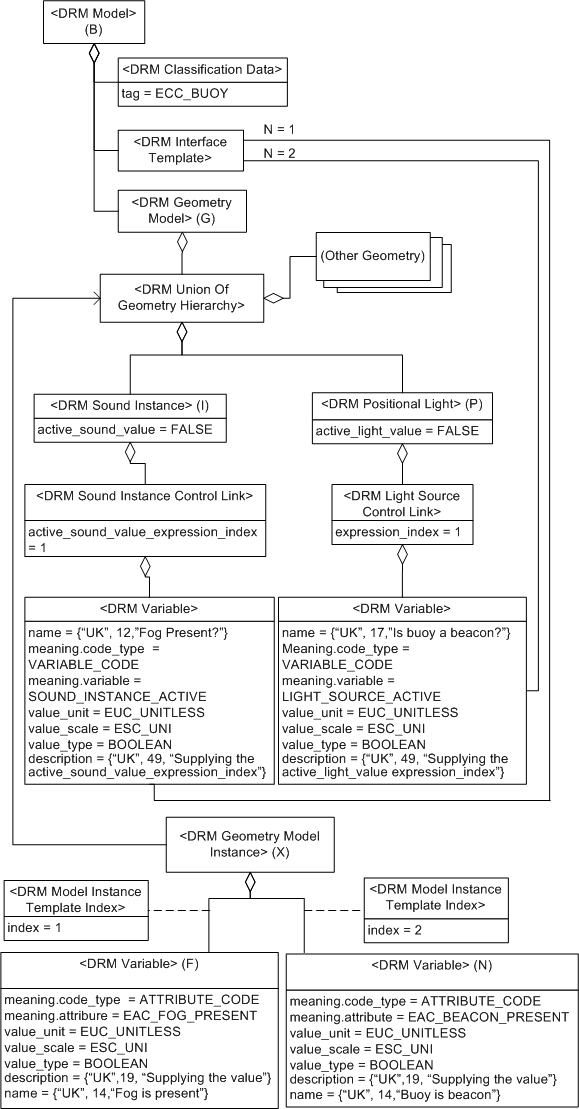
Figure 4.20 -- <DRM Variable> usage example
The <DRM Union Of Geometry Hierarchy> component that organizes the geometry of G specifies a <DRM Sound Instance> component I representing the foghorn and a <DRM Positional Light> component P representing the light. The active_sound_value of I and active_light_value of P are set to FALSE, indicating that the foghorn and light are turned off by default. The <DRM Sound Instance Control Link> component of I allows the foghorn to be turned on or off when B is instantiated. Likewise the <DRM Light Source Control Link> component of P allows the light to be turned on or off when B is instantiated. The index field values of these <DRM Control Link> instances specify which <DRM Expression> component will be used to determine if the foghorn and light will be on. Both the foghorn and light will be controlled by <DRM Variable> instances when instantiated. The <DRM Interface Template> component of B associates with the <DRM Variable> instances under B that have values supplied when B is instantiated in the environment.
The <DRM Geometry Model Instance> X instantiates B in the environment through an association to G. The <DRM Variable> component F represents the existence of fog to be evaluated when B is instantiated and the component N represents whether the buoy is a beacon and has a light. Whether or not the foghorn sound is active depends on <DRM Variable> component F that indicates whether fog is present. Whether or not the light is active depends on <DRM Variable> component N that indicates the buoy is a beacon. The <DRM Model Instance Template Index> link objects on the component relationships specify for which <DRM Variable> instance the value is to be used. The index field of the link object specifies the nth ordered association from the <DRM Interface Template> component of B to the <DRM Variable> instances found under B. Thus, the value for EAC_FOG_PRESENT will control the active_sound_value field and the value of EAC_BEACON_PRESENT will control the active_light_value field.
<DRM Function> instances are used as <DRM Expression> instances for which the value is determined by evaluating arguments and passing them through some function. A <DRM Function> instance aggregates its arguments as a set of ordered <DRM Expression> components, where the exact interpretation of each argument is specified by the specific function. The arguments, together with the specification of the function, determine the value returned by the <DRM Function> instance. The abstract class <DRM Function> has two concrete subclasses: <DRM Predefined Function> and <DRM Pseudo Code Function>. These are described below.
The <DRM Predefined Function> class specifies the function from the Predefined_Function selection data type. These functions fall into various categories as shown in Table 4.7:
Table 4.7 — Predefined function categories
|
Category |
Description |
|---|---|
|
Mathematical constants |
This category includes the value PI. |
|
Unary mathematical functions |
These functions take a single argument. Examples of these include trigonometric functions such as sine and cosine. |
|
Binary mathematical functions |
These functions take two arguments. Examples of these include arithmetic functions such as addition and subtraction. |
|
Other |
A variety of other useful functions are provided. See 5.2.7.30 Predefined_Function for specific information. |
The number and type of arguments required for a <DRM Predefined Function> instance depends upon the function. The arguments of a <DRM Predefined Function> instance are specified by attaching instances of <DRM Expression> as components of the <DRM Predefined Function> instance itself. The components of a <DRM Predefined Function> instance are always its arguments, and are ordered so that the assignment of each to its specific corresponding argument is unambiguous. A corollary is that <DRM Predefined Function> instances that require no arguments have no components. A further corollary is that the number of <DRM Expression> components for a <DRM Predefined Function> instance shall not exceed the number of arguments.
Instances of <DRM Pseudo Code Function> are used to represent functions that are too complex to use <DRM Expression> trees. These include:
These instances contain fields that describe the desired behaviour in human-readable form.
A <DRM Light Source Control Link> instance provides control over the active_light_value field of a <DRM Light Source> instance. This allows the consuming application to turn the light represented by a <DRM Light Source> instance on and off.
<DRM Light Rendering Properties Control Link> provides control over the active_light_value and candela_value field values of the target <DRM Light Rendering Properties> instances. This allows the user to control whether the target is on or off, and if it is on, how bright it is. In addition, if the candela_value is allowed to vary, <DRM Light Rendering Properties Control Link> can specify constraints on the upper and lower limits of the candela value so that there are limits on the maximum and/or minimum brightness. It is not required that control be provided over all four fields. If any of the link fields is zero, the corresponding target field is not controlled.
A <DRM Sound Instance Control Link> instance provides control over the active_sound_value field of a <DRM Sound Instance> instance. This allows the consuming application to turn the sound represented by a <DRM Sound Instance> instance on and off.
A state-related aggregation represents an environmental object that can assume multiple states as described in 4.13.12 State. The remainder of this subclause explains how the aggregation is used in relation to control link objects.
The following example is stated in terms of <DRM State Related Geometry> instances only, but also applies without loss of generality to <DRM State Related Features> instances.
EXAMPLE Consider a <DRM State Related Geometry> instance T. T represents an environmental object that can assume multiple states of the EDCS Attribute described by the state_tag field of T, where each branch of T represents one of the possible states and the active_state_value field of T indicates which branch is currently active. In order for T to be able to assume a state other than that indicated by the value used by the data provider to populate the active_state_value field of T when T was created, T shall have an appropriate <DRM State Control Link> component C. C provides a connection between the active_state_value of T and the controlling <DRM Expression> component E of C, so that the active_state_value of T is determined by the value of E. Since active_state_value is the only controlled field in a <DRM State Related Geometry> instance, the <DRM State Control Link> has exactly one <DRM Expression> component, and its expression_index field value is one as shown in Table 4.8.
Table 4.8 — Example <DRM State Control Link>
| expression_index | 1 |
| mismatch_behaviour | LAST |
Consider a specific building represented by a <DRM State Related Geometry> instance B, where the data provider is concerned with representing the EAC_GENERAL_DAMAGE_FRACTION state of the building. The data provider has chosen to model four damage states: 0% damaged, 25% damaged, 50% damaged, and 100% damaged (totally destroyed), as shown in Table 4.9.
Table 4.9 — Possible state values example
| state_value | 0% | 25% | 50% | 100% |
|---|---|---|---|---|
|
meaning |
building is OK |
some damage |
heavy damage |
a little pile of rubble |
Table 4.10 indicates that the default state of B is 0% damage; that is, completely undamaged. The <DRM State Data> link objects of the branches have the possible field values (meanings given in the bottom row) shown in Table 4.9.
Table 4.10 — Example state specification
| state_tag | EAC_GENERAL_DAMAGE_FRACTION |
| active_state_value | 0% |
B needs a <DRM State Control Link> component C to allow the use of states other than the default of 0% damage as shown in Table 4.8.
As shown in Table 4.11, the <DRM Expression> component of C is a <DRM Variable> instance V, so that whatever value is plugged into V when B is instanced is fed into the active_state_value of B by C.
Table 4.11 — Example expression using a <DRM Variable> instance
| meaning | (VARIABLE, ACTIVE_STATE_VALUE) |
| value_unit | EUC_UNITLESS |
| value_scale | ESC_UNI |
| value_type | FLOAT |
| description | (DEFAULT, 12, "damage state") |
| name | (DEFAULT, 0, "") |
Suppose that a value of 25% is supplied to the <DRM Variable> instance V. B then changes state to 25% damage. Then more damage is done, so that the damage is updated to 45%. This presents a problem, because the data provider has specified each branch with a single matching value, and 45% is not covered by any of the branches. At this point, the mismatch_behaviour of the <DRM State Control Link> instance C comes into play. Since its value is LAST, B will remain in the 25% damage state.
There are two other possible choices for mismatch_behaviour, but they are not appropriate for this example. DEFAULT would have reset B to its default state (that provided by the original unmodified active_state_value), namely, 0% damage. The effect would be that 45% damage would appear to return the building to its intact state, as for that matter, would 99% damage, or any other value not covered by the branches of B. The other possible choice, NONE, acts as an off state. The building would seem to disappear completely if none of the branches matched, then reappear when a matching value occurred. If that had been specified, 5% damage would make the building disappear from sight, but 25% damage would make it reappear.
<DRM CMY Colour Control Link>, <DRM HSV Colour Control Link>, and <DRM RGB Colour Control Link> serve exactly the same purposes for their respective colour models. An understanding of the operation of any of the three is an understanding of the principles underlying the operation of all three. Consequently, only the operation of <DRM RGB Colour Control Link> will be described, with the understanding that the explanation applies to the other two classes in principle.
<DRM RGB Colour Control Link> provides control over the red, green, and blue elements of the rgb_data fields of the target <DRM RGB Colour> instances. A data provider is not required to provide control over all three components. The target component is not controlled if any of the link fields within a <DRM RGB Colour Control Link> instance is zero.
<DRM RGB Colour> instances within the context of a <DRM Colour Table> instance shall not have <DRM RGB Colour Control Link> components, because a <DRM Colour Table> instance does not provide a <DRM Interface Template> instance to allow values to be supplied for <DRM Variable> instances. Data consumers need only concern themselves with <DRM RGB Colour Control Link> instances in the context of <DRM Model> and <DRM Environment Root> instances.
A data provider may wish to provide control over the colour of a <DRM Model> instance, so that every <DRM Geometry Model Instance> instance of that <DRM Model> instance can be given a different colour, allowing the user of the <DRM Model> instance to vary the appearance of model instances without being forced to replicate many <DRM Model> instances that differ only in colour.
EXAMPLE A <DRM Model> instance representing a car may be designed for an environment in which thermal colours are a consideration. In this case, the user might need the ability to change the colour of the car dynamically, as the engine heats up from a cold start or as the engine cools down after being shut off.
A <DRM Translucency Control Link> instance provides control over the translucency_value field of a <DRM Translucency> instance. This allows such visual effects as fading in puddles based on the precipitation rate.
A <DRM Texture Coordinate Control Link> instance provides control over the s and t fields of a <DRM Texture Coordinate> instance. It is not required that control over both fields be provided. Setting a link field (s_expression_index or t_expression_index) within a <DRM Texture Coordinate Control Link> instance to zero specifies that the target field is not dynamically altered.
A <DRM Property Set Index Control Link> instance provides control over the index field value of the target <DRM Property Set Index> instances.
EXAMPLE The appearance of a tree canopy varies according to the season of the year, so a data provider may choose to provide the ability to apply different texture maps and colours to a representation of a tree canopy to represent its appearance in different seasons. This can be achieved by providing a <DRM Property Set Table> instance containing a different <DRM Property Set> instance for each season of the year. Each <DRM Property Set> instance specifies appropriate <DRM Colour> and <DRM Image Mapping Function> instances. The aggregate representing the tree canopy has a <DRM Property Set Index> component that, in turn, has a <DRM Property Set Index Control Link> component. The <DRM Property Set Index> index field may then be used to select the appropriate <DRM Property Set> instance for a given time of year.
A <DRM Colour Index Control Link> instance provides control over the index and intensity_level fields of the target <DRM Colour Index> instances. It is not required that control over both fields be provided. A target field is unaffected by specifying zero for the respective link field within a <DRM Colour Index Control Link> instance.
A <DRM Property Table Reference Control Link> instance provides control over the index_on_axis field of the target <DRM Property Table Reference> instances. This allows the selection of different n-1 dimensional slices of the n-dimensional <DRM Property Table> instance that is referred to by a given <DRM Property Table Reference> instance.
EXAMPLE Consider a <DRM Polygon> instance that specifies the electromagnetic properties of its surface material by a <DRM Property Table Reference> component. If the <DRM Property Table Reference> instance has a <DRM Property Table Reference Control Link> instance, its index_on_axis field value can be changed.
Control links may be used to modify coordinate-components representing locations within a local 3D SRF. Only local 3D SRFs may be modified in this manner.
A <DRM LSR 3D Location Control Link> instance provides control over the u, v, and w elements of the coordinate fields of the target <DRM LSR 3D Location> instances. It is not required that control over all three components be provided. The target component is unaffected by specifying zero for the link fields(u_expression_index, v_expression_index, or w_expression_index) within a <DRM LSR 3D Location Control Link> instance.
EXAMPLE Consider a <DRM LSR 3D Location> instance in a <DRM Model> instance representing a building, where the location represents a point at the foundation of the building. In this case, the data provider wishes to be able to conform each instance of the <DRM Model> to the terrain on which it is instanced, so that the bottom of the building rests on the terrain, regardless of whether the terrain is flat or hilly. The <DRM LSR 3D Location> instance is provided with a <DRM LSR 3D Location Control Link> instance that specifies zero for the u and v values of the target, but a controlling <DRM Variable> instance for the w value.
A <DRM Reference Vector Control Link> instance provides control over the unit_vector field values of the target <DRM Reference Vector> instances. It is not required that control over all three entries of the unit_vector be provided. The target field is unaffected by specifying zero for its corresponding link field (v0_expression_index, v1_expression_index, and v2_expression_index) within a <DRM Reference Vector Control Link> instance.
EXAMPLE 1 A <DRM Reference Vector Control Link> instance is used to specify the normal vector of a <DRM Polygon> instance.
EXAMPLE 2 A <DRM Reference Vector> of type LIGHT_DIRECTION is used to control the direction of a light.
A <DRM Polygon Control Link> instance provides control over the HAT_TEST flag, the COLLIDIBLE flag, the INVISIBLE flag, and the LASER_RANGE_FINDING flag of the polygon_flags field of the target <DRM Polygon> instance. It is not required that control over all flags be provided. A target flag is unaffected by specifying zero for the respective index field within a <DRM Polygon Control Link> instance.
A <DRM Rotation Control Link> instance provides control over the angle field of the target <DRM Rotation> instance. In addition, control over the upper limit and/or lower limit of the rotation angle is also provided through two additional indexes. It is not required that control over all fields be exercised. The target field is unaffected by specifying zero for the respective indexes within a <DRM Rotation Control Link> instance.
A <DRM Scale Control Link> instance provides control over the scale_factor field of the target <DRM Scale> instance. In addition, control over the upper limit and/or lower limit of scale_factor is also provided through two additional indexes. It is not required that control over all three values be exercised. The target field is unaffected by specifying zero for the respective indexes within a <DRM Scale Control Link> instance.
A <DRM Translation Control Link> instance provides control over the translation_amount field of the target <DRM Translation> instance. In addition, control over the upper limit and/or lower limit of the translation_amount is also provided through two additional indexes. It is not required that control over all three values be exercised. The target field is unaffected by specifying zero for the respective indices within a <DRM Translation Control Link> instance.
Metadata can exist at a variety of levels within a transmittal hierarchy, as deemed appropriate by the data producer.
In the DRM, classes that represent metadata provide functionality in one of two categories:
The human-oriented metadata classes of the DRM are designed to comply with geospatial metadata as specified in ISO 19115. Instances of these classes are intended to provide human-readable descriptions of various characteristics of the environmental data represented by the DRM objects of which they are components. The meanings of the fields of these metadata objects are as specified in ISO 19115.� This part of ISO/IEC 18023 does not redefine the meanings of the fields, but instead uses a subset of the fields specified in ISO 19115 within the metadata DRM classes. As a result, there is a correspondence between the DRM classes in this part of ISO/IEC 18023 with their field elements and the data elements in ISO 19115.
The <DRM Responsible Party> class corresponds to the data element CI_ResponsibleParty of ISO 19115. The required information that shall be provided in the fields of <DRM Responsible Party> instances to ensure such correspondence is specified in 7.2.46 Mandatory metadata. The following is the listing of the field elements of the <DRM Responsible Party> and the corresponding ISO 19115 data elements:
Role information is specified by the <DRM Role Data> component containing the role field which is an instance of the ISO 19115 CI_RoleCode data type.
The <DRM Citation> class corresponds to data class element CI_Citation of ISO 19115. The title field shall be provided with information in compliance with the 7.2.46 Mandatory metadata constraint. The following is the listing of the field elements of the <DRM Citation> class and the corresponding ISO 19115 data elements:
Responsible party information is specified by zero or more <DRM Responsible Party> components that correspond to the data element citedResponsibleParty of data class element CI_ResponsibleParty.
The <DRM Spatial Extent> class corresponds to ISO 19115 data element EX_GeographicBoundingBox, specifying the geographic areal domain of a data set. <DRM Spatial Extent> specifies a bounding rectangle (or parallelepiped, if three-dimensional <DRM Location> instances are used) within which all position information in the data set being thus described shall fall.
The DRM mechanisms for providing time-related information serve more than one purpose. As well as providing human-oriented metadata, these mechanisms are used as part of the time-related organizing mechanism. See 4.13.13 Time for details.
The <DRM Identification> class corresponds to the data class element MD_Identification of ISO 19115 and is constrained by 7.2.46 Mandatory metadata to, at a minimum, provide information in its abstract section. The following is the listing of the field elements of the <DRM Identification> class and the corresponding ISO 19115 MD_Identification data elements:
The <DRM Data Quality> class corresponds to the data class element DQ_Element of ISO 19115 used to provide a general assessment of the quality of the environmental data being described. The following is the listing of the field elements of the <DRM Data Quality> class and the corresponding ISO 19115 data elements:
The lineage information of ISO 19115 in data element LI_Lineage corresponds to the <DRM Lineage> class in the DRM and may contain instances of <DRM Source> and/or <DRM Process Step>. A <DRM Source> instance, representing information about a particular data source (whether an original or derived data source), has a <DRM Citation> component to refer to the source data set, and a <DRM Time Interval> component specifying the time period for which the source data was applicable. The description, scale, and contribution information about the data source is represented directly in the fields of the <DRM Source> class itself.
A <DRM Process Step> instance, describing a single processing step during the derivation of the data set being described, may be associated to any applicable <DRM Source> instances via appropriate <DRM In Out> link objects that indicate whether each <DRM Source> instance was an input or output of the <DRM Process Step> instance. The <DRM Process Step> class provides a human-readable description of the process directly in its own fields, as well as a mandatory <DRM Absolute Time> component specifying the date (and, optionally, time) at which the process was performed. A <DRM Process Step> instance may also specify a <DRM Responsible Party> instance for the process.
The <DRM Keywords> class corresponds to the data element MD_Keyword of ISO 19115, specifying a keyword_count, keyword_array, and type as fields, where 7.2.46 Mandatory metadata constrains the data provider with further restrictions. The type field specifies the subject matter being used to group similar keywords in a given instance of <DRM Keywords>. The keyword_count field specifies the number of entries in keyword_array, each entry of which specifies a commonly used word, formalized word, or phrase used to describe the subject.
The <DRM Legal Constraints> DRM class corresponds to the MD_LegalConstraints data element of ISO 19115 with fields corresponding as follows:
The <DRM Security Constraints> DRM class corresponds to the MD_SecurityConstraints data element of ISO 19115 with fields corresponding as follows:
The 7.2.46 Mandatory metadata constraint requires only that a user specify the classification information, since an unclassified data set will not have any other information. No specialized data types, such as enumerations, are provided for the system or classification fields, since there is no worldwide standard for security information of this kind and many countries may have multiple incompatible systems used for different purposes.
The <DRM Browse Media> class corresponds to the ISO 19115 data element MD_BrowseGraphic, a graphic providing an illustration of the data set being described, but has been modified in this part of ISO/IEC 18023 to enable transmittals to be self-contained. A <DRM Browse Media> instance separates the file name and file type of MD_BrowseGraphic by using the fields media_format and media_urn.
The second category of metadata represents summary information about the structure of a transmittal that can be used to automatically make processing decisions based on the content of a given transmittal. This category of metadata is represented by the various summary classes of <DRM Base Summary Item> information is accessible only at a high level. The <DRM Transmittal Root>, <DRM Environment Root>, and <DRM Model> instances of a transmittal are the items that can be supplied directly with summary information. Such information can be provided in as much detail as desired.
Using the concrete subclasses of <DRM Base Summary Item> provides ummary information in the following areas:
Each is described below.
Every <DRM Transmittal Root> instance provides a <DRM Transmittal Summary>. The information provided by a <DRM Transmittal Summary> instance provides a summary of the contents of a transmittal. Many of the fields of a <DRM Transmittal Summary> instance specify whether various kinds of data are present in <DRM Environment Root> instances, <DRM Model> instances, both, or neither within the transmittal being summarized. The kinds of information include features, geometry, and/or geometry topology.
NOTE There is no feature_topology_present field, since the presence of features automatically ensures the presence of feature topology.
The data_tables_present field does not specify whether a <DRM Data Table Library> instance is present, but whether <DRM Data Table> instances are present within the context of any <DRM Environment Root> or <DRM Model> instance.
EXAMPLE If <DRM Property Grid> instances are present under a <DRM Environment Root> instance, but no <DRM Model> instances contain any <DRM Property Grid>, <DRM Mesh Face Table>, or <DRM Property Table> instances, this field value would be set to ENVIRONMENT_ROOT.
The priority_values_present field specifies whether <DRM Rendering Priority Level> instances have been provided. If not, the end user may need to derive various rendering priority information since it is not provided explicitly.
The terrain_lods_present field specifies whether terrain data organized by level of detail has been provided. This data may be in the form of <DRM Property Grid> instances, <DRM Polygon> instances, or other primitives. The organization is not specified by this flag, although it can be specified using other summary information.
The two_D_features_flag field specifies whether <DRM Primitive Feature> instances specified in reference to <DRM Feature Topology> instances using <DRM Location 2D> instances are present.
The mobility_values_present and thermal_values_present fields specify whether <DRM Property> instances referring to EACs corresponding to mobility and thermal information have been provided, and if so, in which context.
The models_present, images_present, sounds_present, and symbols_present fields are flags indicating whether instances of the corresponding <DRM Library> subclasses are present.
The colours_present flag indicates whether the colour_model flag is actually meaningful. A transmittal containing no <DRM Colour> instances, such as a transmittal with geometry consisting only of <DRM Property Grid> instances and various organizational hierarchy, contains no meaningful colour information.
The EDCS_usage_list_is_complete flag is discussed in 4.17.3.3 EDCS usage summary, as are the optional <DRM EDCS Use Summary Item> components. provided by a <DRM Transmittal Summary> instance.
The optional <DRM DRM Class Summary Item> components are discussed in 4.17.3.4 DRM class usage summary.
Each <DRM Environmental Domain Summary> instance, if present, specifies an ECC (possibly qualified as per 4.8.2.2 Qualification) that applies to the entire transmittal.
Within the scope being summarized, a <DRM EDCS Use Summary Item> instance can specify either an ECC with an optional set of EACs, or just an individual EAC. If the ECC is qualified, the <DRM Classification Data> representing it is qualified with <DRM Property Value> instances rather than representing the qualifiers as <DRM Property Description> components of the <DRM EDCS Usage Summary Item>.
A list of <DRM EDCS Use Summary Item> instances can be provided for:
For a <DRM Transmittal Summary> instance, the EDCS usage summary, if provided, may be comprehensive, spelling out the uses of all EACs and ECCs that occur within the transmittal, or the summary may omit items. The EDCS_usage_list_is_complete field in <DRM Transmittal Summary> indicates which is the case.
A <DRM DRM Class Summary Item> instance indicates the presence of instances of the class corresponding to its drm_class field value within the following:
A <DRM DRM Class Summary Item> instance may be provided with a list of <DRM EDCS Use Summary Item> instances to summarize EDCS usage among the instances of the specified class within the scope being summarized.
A <DRM Hierarchy Summary Item> instance and/or a <DRM Transmittal Summary> instance can be provided with a list of <DRM DRM Class Summary Item> instances, representing classes used in the context being summarized. By the 7.2.52 Non-overlapping DRM class summary items constraint, each <DRM DRM Class Summary Item> instance in such a list is required to have a unique field value for its drm_class field within that list to prevent repetition of information.
A <DRM DRM Class Summary Item> instance has an optional <DRM SRF Summary> component. A <DRM DRM Class Summary Item> instance is constrained so that such a <DRM SRF Summary> component may be present only if the drm_class field of the <DRM DRM Class Summary Item> instance corresponds to a class that specifies SRF parameters. Each <DRM SRF Summary> instance then corresponds to a specific SRF specified by an instance of that class somewhere in the context being summarized.
A hierarchy summary (that is, a tree of <DRM Hierarchy Summary Item> instances and their accompanying information) can only be provided for instances of those classes that can provide access to a <DRM Geometry Hierarchy> or <DRM Feature Hierarchy> instance, specifically only for <DRM Environment Root> and <DRM Model> instances. The 7.2.40 Hierarchy summary constraints ensures that such hierarchy summary information, if provided, will correspond to the hierarchy that it summarizes. A <DRM Environment Root> or <DRM Model> instance may summarize either its feature hierarchy and/or its geometry hierarchy but may not provide a summary of a hierarchy that is not present.
EXAMPLE An empty <DRM Model> instance, having no hierarchies, is not permitted to have a hierarchy summary.
A hierarchy summary shall be no deeper than the hierarchy that it summarizes. Thus, at the point where the hierarchy consists only of primitives, no further <DRM Hierarchy Summary Item> instances shall exist.
Each level k of a hierarchy summary shall correspond to level k of the hierarchy being summarized. Any associations from <DRM Hierarchy Summary Item> instances at level k shall be to hierarchy instances at level k in the hierarchy being summarized. The drm_class field of <DRM Hierarchy Summary Item> indicates the class of instances being summarized. The multiplicity_meaning and multiplicity field values indicate how many instances at that level are being summarized (possibly exactly, possibly only indicating an order of magnitude, as specified by multiplicity_meaning).
A <DRM Hierarchy Summary Item> may provide a DRM class summary in the form of a list of <DRM DRM Class Summary Item> instances, indicating the DRM classes instanced within the context of the particular hierarchy instance or group of instances being summarized. A <DRM Hierarchy Summary Item> may also provide an EDCS usage summary in the form of a list of <DRM EDCS Usage Summary Item> instances, indicating usage of EACs and ECCs within the context being summarized.
A hierarchy summary is not required to be as deep as the corresponding hierarchy.
In addition to any hierarchy summary that may be present, a <DRM Model> instance or <DRM Environment Root> instance may be provided with a list of <DRM Primitive Summary Item> instances. These concepts provide different functionality. A <DRM Primitive Summary Item> instance represents a common pattern of primitive instances that appear within the scope being summarized, as well as indicating the number of occurrences of the pattern.
EXAMPLE A <DRM Primitive Summary Item> instance can be used to indicate quadrilateral <DRM Polygon> instances wherein each <DRM Vertex> instance has a <DRM Texture Coordinate> instance and each such <DRM Polygon> instance has a <DRM Image Mapping Function> instance and a <DRM Property Value> instance.
A <DRM Primitive Summary Item> instance may also be provided with an EDCS usage summary in the form of a list of <DRM EDCS Usage Summary Item> components, indicating patterns of EDCS usage occurring within the pattern of primitive objects being summarized.
The smallest valid and compliant transmittal shall contain at least the <DRM Transmittal Root> along with a few required instances of metadata such as <DRM Citation>, <DRM Responsible Party>, <DRM Identification>, <DRM Data Quality>, and <DRM Transmittal Summary>.
A transmittal in turn may contain zero or more <DRM Environment Root> instances, as well as an optional instance of each <DRM Library> subclass.
Primitive data, along with a variety of other supporting data items (including attributes, organizational objects, and others) may be found as aggregated data under appropriate <DRM Environment Root> or <DRM Library> instances.
A <DRM Transmittal Root> instance is the hierarchical root of a given transmittal. It contains fields that describe the version of DRM and EDCS to which the transmittal conforms. It also has a number of required DRM objects that shall be provided. The smallest valid and compliant transmittal shall have a <DRM Transmittal Root> instance along with its required subordinate components.
In addition, a <DRM Transmittal Root> can have a collection of optional components.
A <DRM Environment Root> instance is the hierarchical root of all data instanced in a transmittal within the same SRF (except that found under a <DRM Library> instance). It specifies the characteristics of the SRF to which it is bound and the spatial extents of the region or volume that the corresponding content occupies. A <DRM Environment Root> also provides supporting instances of other DRM classes, such as metadata, that clarify the intended interpretation of the data rooted at the <DRM Environment Root> instance.
The srf_context_info field of a <DRM Environment Root> instance specifies the SRF in which the <DRM Feature Hierarchy> and/or <DRM Geometry Hierarchy> components of the <DRM Environment Root> instance are specified. A <DRM Environment Root> instance may not be empty.
In the case where a given <DRM Transmittal Root> instance specifies multiple <DRM Environment Root> components, the srf_context_info field of each such <DRM Environment Root> component shall be distinct. This provides an unambiguous mechanism for representing an environment that may span multiple GCS cells or UTM zones.
A data provider may have applied coordinate conversion or transformation operations to the environmental data contained in the scope of a <DRM Transmittal Root> instance before the environmental data was represented using the DRM. An instance of <DRM Reference Origin> may be supplied to correlate environmental data from producer to consumer by specifying the original SRF in which the environmental data was represented and an instance of <DRM Location> specifying the origin of the environmetnal data in the original SRF.
This part of ISO/IEC 18023 specifies a standard API for manipulating transmittals.
The API supports many capabilities including:
The API provides retrieval functions that operate on both transmittals and their DRM objects. The API provides private data types to work with these data elements. An instance of the Transmittal private data type (see 5.4.8 Transmittal) provides access to a transmittal. An instance of the Object private data type (see 5.4.3 Object) provides access to DRM objects within an open transmittal.
All API functions access a DRM object by using an instance of the Object private data type. Such an instance is termed an object handle. Object handles identify implementation-dependent information about the object. Once an object handle is retrieved by the API, it can be used to retrieve additional information from the DRM object such as field data and handles to associates, aggregates, and components.
The following DRM classes are supported by class-specific API functions:
<DRM Data Table> may not be accessed via an object handle since <DRM Data Table> is an abstract DRM class. Instances of the other four DRM classes all represent complex data that requires special handling. The API provides for the creation, retrieval, and storage of the data associated with these four DRM objects.
API functions operate on transmittals and their contents. The API functions, 8.3.62 OpenTransmittalByLocation and 8.3.63 OpenTransmittalByName, open a transmittal and return an instance of the private data type Transmittal (see 5.4.8 Transmittal). Such an instance is termed a transmittal handle. The transmittal handle may then be passed to other API functions to identify the transmittal upon which the functions are to operate. A transmittal handle becomes invalid when it is passed to the 8.3.5 CloseTransmittal function that closes a transmittal. When 8.3.5 CloseTransmittal is invoked, all resources associated with that transmittal are released.
An iterator is a mechanism that simplifies traversal of DRM object relationships. The following API functions are provided for creating and initializing an iterator for traversing each type of relationship:
The function returns an instance of the Iterator private data type (see 5.4.2 Iterator). Such an instance is termed an iterator handle. The iterator handle is subsequently used by 8.3.31 GetNextObject to return an object handle.
The resources associated with an iterator (including its iterator handle and any unretrieved object handles) are freed by invoking 8.3.10 FreeIterator.
DRM objects may be selectively retrieved from a transmittal by specifying search criteria in the form of filters. 8.3.7 CreateSearchFilter creates a search filter and returns an instance of the private data type Search_Filter (see 5.4.6 Search Filter). Such an instance is termed a search filter handle. The search filter handle is then passed as a parameter when an iterator is created. The search criteria will be applied during the traversal of that iterator.
ITR supports the specification of relationships between DRM objects contained in different transmittals.
EXAMPLE ITR allows a DRM object in one transmittal to associate to a DRM object in another transmittal.
To create an ITR relationship to a DRM object, the DRM object that is being referenced shall be published and the transmittal to which the DRM object belongs shall have a URN. Publishing a DRM object consists of associating the DRM object with a specified string termed a label by invoking 8.3.64 PublishObject. A URN for a transmittal is specified by invoking 8.3.82 SetTransmittalName. If the relationship between DRM objects is aggregation, the aggregating DRM object and the aggregated DRM object shall both be published, and the transmittals containing both DRM objects shall have URNs. Bidirectional associations may be specified in a similar manner.
Resolution is the process of attempting to retrieve the transmittal and the DRM object within that transmittal using the URN and label provided. A DRM object is termed unresolved if it cannot be retrieved. Conversely, a DRM object is termed resolved if it can be retrieved. All DRM objects in an open transmittal are, by definition, resolved. Control of the resolution process is specified by a parameter of data type ITR_Behaviour (see 5.2.6.11 ITR_Behaviour).
Relationships that use ITR still follow the DRM relationship rules. Those DRM objects that can create relationships through ITR are limited by the DRM constraint, 7.2.59 Publishable object. This constraint specifies the DRM classes whose instances can be used in 8.3.64 PublishObject and thus published.
The API supports storage and retrieval of environmental data in multiple encodings as defined in this International Standard. The API provides, for each applicable function, a parameter of data type Encoding that specifies which type of encoding is applicable for the operation of the function.
EXAMPLE To open transmittal A, the encoding parameter specifies in which encoding transmittal A is stored.
Private data types are data types that have objects (methods and resources) that implement the functionality associated with the private data type. Each instance of a private data type has an associated handle that is used to access the corresponding object. Handles may be replicated to provide access through alternate means.
EXAMPLE The Iterator private data type corresponds to the resource that implements iterator functionality according to the parameters associated with each instance.
A Create function associated with the private data type creates an object and returns a handle. Handles may also be returned by functions that provide access to an existing object. Resources (normally memory resources) are associated with each handle and with each object. The resources used by the object and the resources used by its handle(s) are separate. Resources for an object are allocated when the Create function is called. This also allocates resources for a handle that is returned by the Create function. Resources associated with a handle are freed when the Free function that corresponds to the private data type is invoked. The resources associated with the object are freed when there are no handles that access the object.
Before a DRM object can be accessed, access to the transmittal shall be established using either of the two functions that open transmittals:
Once a transmittal has been opened, the root object may be retrieved by using 8.3.45 GetRootObject. If the open function created a new transmittal, the root object can be set by invoking 8.3.78 SetRootObject.
Once the root object has been obtained, access to other DRM objects is possible.
When access to a transmittal is no longer needed, the transmittal may be closed by invoking 8.3.5 CloseTransmittal.
The following functions are used to create and remove DRM objects:
New DRM objects may be placed in a transmittal by performing the following steps::
The DRM object instances, fields, and handles of DRM objects may be retrieved from a transmittal using the following functions:
Retrieval of two other types of DRM object data exist. Retrieval of data table data is described in 4.19.2.7 Access and modification of data table and mesh face table data. Retrieval of image data is described in 4.19.2.8 Access and modification of image data.
For each type of DRM relationship (aggregate, component, and associate), there is a corresponding iterator type. The functions that provide iterator functionality are:
Iterators provide the following mechanisms for selectively returning DRM objects:
Each is specified below.
A search filter is an instance of the private data type, 5.4.6 Search_Filter. The search filter specifies a set of rules that determine which DRM objects may be returned from a search of a transmittal. A search filter is specified during the initialization of an iterator. The 8.3.7 CreateSearchFilter function creates and initializes a search filter with search rules as specified in 5.3.3.220 Search_Rule. The 8.3.11 FreeObject function is used to free a search filter. Search filters may be used for the following types of searches:
Search filters can be used in the initialization of all three types of iterators.
A spatial extent is a parallelepiped specified by an instance of 5.3.3.219 Search_Bounds. This spatial extent is passed to 8.3.8 CreateSpatialSearchBoundary, which allocates resources necessary for performing the search, returning a search boundary handle (an instance of 5.4.5 Search_Boundary). The search boundary handle is then passed to 8.3.56 InitializeComponentIterator. The spatial search evaluation operates on the <DRM Location> instances that are components of other DRM objects to determine how an object intersects the search boundary.
Additional parameters that define the search criteria include:
DRM objects can also be evaluated separately from iterators using 8.3.9 DetermineSpatialInclusion.
Searching may be done by inclusion or exclusion of branches in a hierarchy. Three different kinds of branch selection are supported:
When selective inclusion is enabled, the select_parameters parameter specifies the link object data that indicates which branches are to be included. This parameter of 8.3.56 InitializeComponentIterator determines which types of hierarchies are to be included and under what criteria those hierarchies are to be included.
A unique and persistent object ID (a string) for each DRM object is created by the implementation and shall be available on request. The following two functions support object IDs:
For greater efficiency, multiple DRM objects may be retrieved by a single function call. The following functions support this capability:
The following inquiry functions are provided for obtaining information about DRM objects, transmittals, and API constructs:
The field values of newly created DRM objects may be specified using 8.3.66 PutFields. The field data of an existing DRM object may be modified using this function if the transmittal has been opened in an access mode that allows modification.
Relationships between DRM objects within a transmittal may be created or removed using the following functions:
The selected portions of instances of <DRM Data Table> subclasses may be specified or retrieved using the following functions:
The data associated with an instance of <DRM Image> may be specified or retrieved using the following functions:
Since an instance of the 5.4.3 Object data type is a handle to DRM objects, it is not the DRM object, but just a reference or pointer to the actual DRM object in the transmittal. The function 8.3.4 CloneObjectHandle provides a new handle to an existing DRM object.
ITR is supported by the following functions:
An application may request that location and/or colour data contained in a transmittal be converted during retrieval into the form needed by the application using the following functions:
As a convenience for processing while traversing transmittals, the API allows data defined by the processing application to be associated with a DRM object. This data is called user data and is managed by the application. It is not considered part of the transmittal. Once the application associates some user data to a DRM object, the API maintains the association until the DRM object is freed. The most common use case for user data involves objects with multiple handles in the API. User data associated with a DRM object may be retrieved using any handle to that DRM object. Also, since the application is responsible for memory management of the user data and there are often multiple handles to DRM objects with user data, it is necessary for the application to determine the number of outstanding handles before a DRM object is freed to determine whether or not to free its user data. The following functions support user data.
Errors are handled by two mechanisms. In the first mechanism, an application may register an error callback function that will be called when a function fails. In the second mechanism, error information may be retrieved upon request. Each mechanism is described below.
The Status_Logger data type specifies the function definition for user-defined callback functions. The callback function shall support the following parameters:
A function meeting the Status_Logger signature can be registered through the API to be called when an API function fails. The following functions are used to provide this capability:
The API specifies the function 8.3.29 GetLastFunctionStatus to return the status of the last API function that was called along with a string describing the function. This part of ISO/IEC 18023 does not specify the format for the explanatory string nor the level of information contained within.
To ensure a consistent subset of SEDRIS functionality for a widely used set of application-specific requirements, this part of ISO/IEC 18023 supports the concept of profiles. A profile is a formal specification of:
The default profile is specified that incorporates all of the functionality specified in this part of ISO/IEC 18023 but does not include any registered items. An implementation of SEDRIS is free to exceed the requirements of any profile to which it claims conformance.
Additional profiles may be specified by amending this part of ISO/IEC 18023.
The orderly evolution of SEDRIS functionality is supported through the registration of instances of the following in the International Registry of Graphical Items1:
Each of these is described in more detail below.
Registration is accomplished by preparing a registration proposal as specified in ISO/IEC 9973 and submitting this proposal using the procedures described therein.
Selection item data types provide for the specification of three types of values:
Standard items are those values for a selection item data type that are specified in this part of ISO/IEC 18023. Support for standard items is as specified in this part of ISO/IEC 18023.
Registered items are those values for a selection item data type that have been submitted to the International Registry of Graphical Items using the procedures specified in ISO/IEC 9973. There is no requirement to support registered items unless they are explicitly required by a particular profile and that profile is being supported by an implementation. Implementations not supporting a particular registered value shall ignore such values and report the occurrence of such values as a non-fatal error.
Implementation dependent values are those supported by a particular implementation. They should solely be used for development or experimental purposes. Implementations separate from that which specifies the implementation dependent value shall ignore such values and report the occurrence of such values as a non-fatal error.
A registration proposal for selection data item selectors shall contain the name for the selector as well as the meaning associated with that name. Such meanings shall not duplicate existing selectors and shall not modify the intent of the selection data item data type. The selector number assigned to the selector shall be as specified by the Registry of Graphical Items.
New members of set data types may be added by registration. A registration proposal for a set member shall contain the name for the set member as well as the meaning associated with that name. Such meanings shall not duplicate existing set members and shall not modify the intent of the set data type. The position of new set members in the list of set members shall be as specified by the Registry of Graphical Items. Typically, each new member is appended to the list following either the last standard set member or the last previously registered set member, as appropriate.
Only standard set members and registered set members may be in the set. Implementation dependent set members are not allowed.
1 At the time this International Standard was published, the ISO International Registration Authority for Graphical Items was the United States National Geospatial-intelligence Agency (NGA). The mailing address was: Registration Authority, National Geospatial-intelligence Agency, c/o Joint Interoperability Test Command, Building 57305, Room 263A, Fort Huachuca, Arizona 85613-7020. US.
http://standards.iso.org/ittf/PubliclyAvailableStandards/ISO_IEC_18023-1_Ed1.html